Before you begin, you should know which wiring scheme you will be using. The only difference between 568A and 568B wiring is that pairs 2 and 3 (orange and green) are swapped. If you are unsure which one to use then you should go with the 568B diagram. It is the 568B diagram that we demonstrate in this tutorial and the 568A wiring is shown in the diagrams below mainly for illustration. In our estimation the 568B connection is used in over 99% of all straight through applications. Know that using either the A or B standard will produce a "straight through" connection that should work for any Ethernet or POE (power over Ethernet) application. Therefore do not sweat over the choice.
LANshack.com was the very first e-commerce website to offer free online tutorials for cable connections. To say that our articles have been popular over the span of many years would be an understatement. But time marches on and we now have three major updates. For one, we have updated this very popular tutorial, and two, we now have a video tutorial to go with it. But most importantly, we have now developed a totally new system for termination cables called the QuickTreX™ PRO System™.
568-B Wiring
| Pair # | Wire | Pin # |
|---|---|---|
|
1White / Blue
|
White / Blue | 5 |
| 4 | ||
|
2White / Orange
|
White / Orange | 1 |
| 2 | ||
|
3White / Green
|
White / Green | 3 |
| 6 | ||
|
4White / Brown
|
White / Brown | 7 |
| 8 |
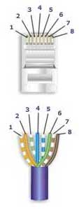
568-A Wiring
| Pair # | Wire | Pin # |
|---|---|---|
|
1White / Blue
|
White / | 5 |
| 4 | ||
|
2 White / Orange
|
White / Orange | 1 |
| 2 | ||
|
3White / Green
|
White / Green | 3 |
| 6 | ||
|
4White / Brown
|
White / Brown | 7 |
| 8 |
How to make a Category 5 Cat 5E or Cat 6 Patch Cable: Install RJ-45 Connectors: Easy Loadbar Method
Below are the steps outlined in the video.
Once you get good at it, with some dexterity the assembly time will be less than a minute.1 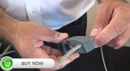
Start at about 1.5" to 2" back on the cable and skin the cable's jacket. Circle the cable with the tool 1-2 times. |
2 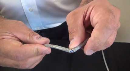
Remove the stripper tool and gently bend the cable where it was scored by the tool in both directions (back and forth). The cable's outer jacket should just pull off. |
3 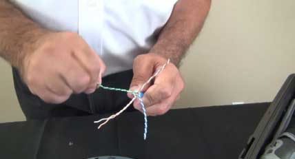
Begin to untwist each pair |
4 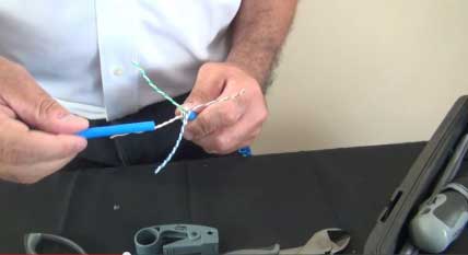
Use the discarded piece of the cable's jacket to complete the process. Leave about 1 twist at the end. |
5 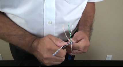
Straighten out the wires. Use of a blunt edge tool like a long nose pliers will help greatly and save your fingers. |
6 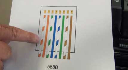
Refer to the diagram that you intend to use. In this case, we are using the 568B scheme. |
7 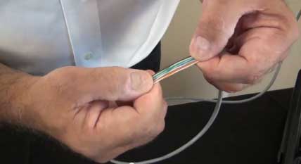
Put the wires in the appropriate order and get them as straight and close together as possible by running them through your fingers |
8 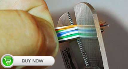
While holding the group of wires in perfect fashion, cut off about 0.25" from the end to get the wires ready to go into the loadbar. |
9 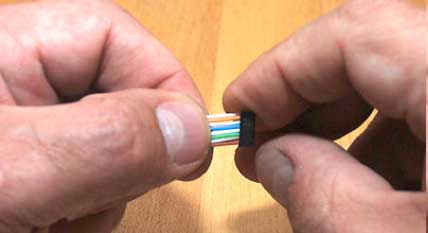
Insert the wires into the loadbar with the hollow end of the loadbar facing the wires. Slide the loadbar down on the wires |

Gently jiggle the wires from side to side while maintaining pressure on the bundle and they will all come through easily.
|
||
10 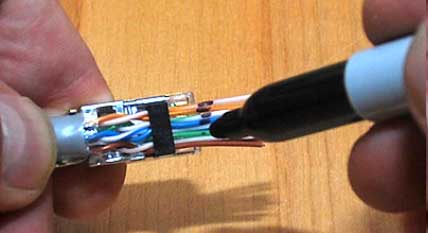
Use the electrician's wire scissors to cut the wires straight across at the point where you made the mark. |
11 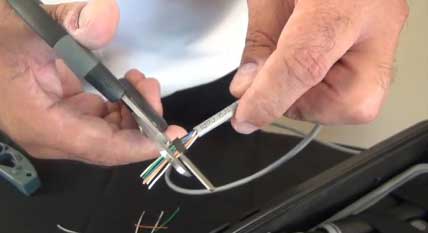
Use the electrician's wire scissors to cut the wires straight across at the point where you made the mark. |
12 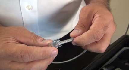 > >
With the Orange pair furthest away from you and the Brown pair closest, slide the connector on to the assembly with the pins facing up and the locking clip facing down. Push the assembly into the connector with a slight wiggling motion to make the ends of the wires go all the way to the end of the connector. It may be necessary to use moderately firm pushing to make this happen. At this point it is advisable to use a magnifying glass or jeweler's loop |
13 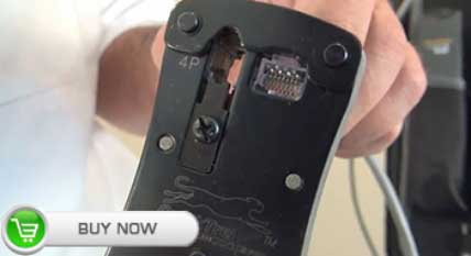
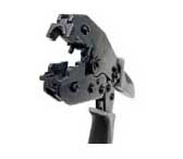
Insert the connector into the crimper and keep pressure on the cable (pushing it in to the connector) until the crimp is complete. Use a high quality Industry Standard Crimper such as our QuickTreX® Professional "Five In One" Modular Crimping Tool |
14 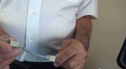
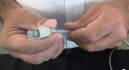
If you intend to use cable boots, slide them onto the cable now before installing the opposite connector. Boots are completely optional. |
15 
Repeat the process and install the connector on the opposite end. |
16
 |
Test the cable with a 4-pair type Cable Tester. |
|
Notes Regarding Making Category 5 Patch Cable
1) The RJ-45 plugs are normally made for either solid conductors or stranded conductors. It is very important to be sure that the plug that you use matches the conductor type. It is extremely difficult to tell the difference between the two by looking at them. When you buy these plugs, be sure to categorize, and store them carefully. Using the wrong type can cause intermittent problems. The QuickTreX™ Category 5E, 8 Conductor Modular Plugs, OR QuickTreX™ Category 6, 8 Conductor Modular Plugsthat we sell are rated for both Solid and Stranded cable.
2) Ordinarily, it would be taboo to untwist the pairs of any category 5 or 6 cable. The one exception to this rule is when crimping on RJ-45 plugs. It would be impossible to insert the wires into the channels without first untwisting and straightening them. Be sure not to extend the un-twisting, past the skin point. If you do it properly, you will wind up with no more than 1/2" of untwisted conductors (up to 1/2" of untwist meets the cat 5 or 6 specification).
3) If the completed assembly does not pass continuity, you may have a problem in one, or both ends. First try giving each end another crimp. If that does not work, then carefully examine each end. Are the wires in the proper order? Do all of the wires fully extend to the end of the connector? Are all of the pins pushed down fully. Cut off the suspected bad connector, and re-terminate it. If you still have a problem, then repeat the process, this time giving more scrutiny to the end that was not replaced.
Controversies And Caveats: Category 5, 5E, And Cat 6 Patch Cables
568B vs. 568A
For patch cables, 568-B wiring is by far, the most common wiring method. Virtually all pre-assembled patch cables are wired to the B standard. There is no difference in connectivity between 568B and 568A cables. Therefore, a 568B patch cable should work fine on a 568A cabling system, and visa-versa.
Re-use of old cables
We have seen this happen time and time again. Perfectly good patch cables that have been working fine for years, get removed from their installation, and re-installed on the same, or different network. The result can be a nightmare. What happens is that the cable, over time, adapts to the way that it is bent in it's original installation. When these cables are removed and re-installed, they can either completely lose their connection, or develop intermittent problems. This is due to stresses that may be opposite to what they were originally subject to. If the integrity of your network is more valuable than the price of new patch cables, then we strongly suggest that you use brand new cables for all closet cleanups, network moves, etc.
Stranded vs. Solid wire
Almost all patch cables that are made have stranded wire. Stranded wire is normally specified for use in patch cables due to its superior flexibility. There has been some talk recently, in the technical sector of the structured wiring community, regarding the possible use of solid conductors for patch cables. The reason for the spotlight on solid wire is that it is supposedly more stable, under a variety of conditions. Please note that we now offer custom Solid copper category 5E patch cables in Plenuminsulation in lengths of up to 295 feet. These cables are suitable for use in air handling (Plenum) ceilings and environments.