SALES & ORDERS
Custom Cable Manufacturing in the USA Since 1997
Home of 
Free Ground shipping on orders over $250

Use code SHIP4FREE Exclusions Apply
Important!
Eligible Products Only | Free Shipping Exclusions May Apply to Heavy, Electronics & Bulky Items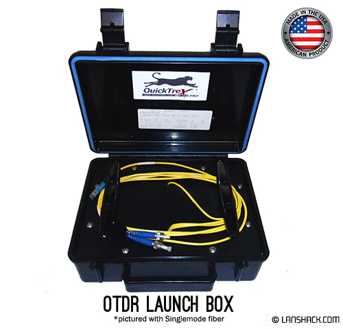


Add Related Products

Pre-Term Fiber Assemblies

MTP Trunk Assemblies

MTP Fanout Cables

MTP Cassettes

Fiber Optic Enclosures

Fiber Optic Patch Cables

Ethernet Patch Cables

Ethernet Cable Bundles

Unterminated Fiber By The Foot
Network Configurator™
Use LANShack’s state of the art network designer tool to completely build your network from scratch.

What product are you looking for?
Pre-Term Fiber Assemblies
MTP Trunk Assemblies
MTP Fanout Cables
MTP Cassettes
Fiber Optic Enclosures
Fiber Optic Patch Cables
Ethernet Patch Cables
Ethernet Cable Bundles
Unterminated Fiber By The Foot
OTDRs are used on outside plant cables to check the loss of each splice and locate any stress points that were caused during installation. OTDRs use the backscattered light of the fiber to indicate loss. With an installed cable plant the OTDR trace will show every connector splice, break, and anomaly in the fiber.
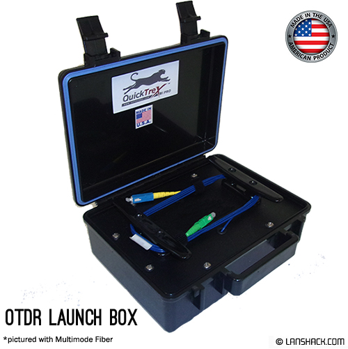
The OTDR Launch Box acts as a companion to OTDR test equipment. There are a few reasons to use a launch box (also know as a “launch cable” or “pulse suppressor”). One, the launch cable helps avoid problems with the dead zone, or the area close to the OTDR which causes an overload from the crosstalk between the instrument and the reflectance from the connector face of the OTDR. The long recovery time means the OTDR cannot make useful measurements near the instrument itself. The launch cable allows time for the OTDR trace to settle down after the test pulse is sent into the fiber so the beginning of the cable being tested can be analyzed.
Second the launch cable provides a reference to push out the first connector of the cable under test so that a picture of the fiber can be taken, as it acts as a reference point for the first connector on the cable under test to determine its loss.
The assembly in the launch box is a simplex bare glass fiber which is a specified length (generally 100 meters for Multimode and 300 meters for Singlemode). The fiber is a fixed length and is terminated with one connector type for the OTDR and the other to match the coupler that the cable under test will be plugged into. The connectors have a standard UPC polish, but APC polish can be added to SC, LC, or FC connectors. The fiber and the connectors are both Genuine Corning brand material, and this product is made in the USA at the time of the order to your specifications. If you need a lenght that is not a standard option, just email [email protected] for a custom quote.
Specs:
Applicable Temperature Restrictions:
Storage temperature: -40 to +70degrees Celsius
Operating temperature: 0 to +70degrees Celsius
Multimode 62.5/125 (850/ 1300nm)
Max attenuation (dB/km): 3.75/1.5
Typical attenuation (dB/km) : 3.0/1.0
Multimode 50 /125 (850/ 1300nm)
Max attenuation (dB/km): 3.5/1.5
Typical attenuation (dB/km) : 3.0/1.0
Singlemode (1310/ 1550nm)
Max attenuation (dB/km): 1.0/.75
Typical attenuation (dB/km) : 0.5/0.4
Connector Physical Contact Specifications:
All terminations measured per BELLCORE GR-326-CORE
Typical radius of curvature 10-30nm
Typical apex offset < 50uM
Fiber undercut/protrusion +/- 50nM
Maximum insertion loss -.5dB
Typical return loss -55dB
Case Composition:
High density polyethylene
Neoprene enviromental seal O-ring
Butterfly twist latches
Spring-loaded handle
Meets ATA-300, Category 1, & Certain Military Specifications
Videos
When You Place An Order

Step 01
Place Your Order
Our team processes your order within 24 business hours.

Step 02
Get Notifications
You receive emails about your order status.

Step 03
Track Your Order
Get tracking on your shipment until delivery.
Product Reviews (18)
5
5
4
3
2
1
WHEELER ELECTRIC
Quick and thorough order completion - had exactly what we needed - right price and right on time!!!
GARG
First class product and service
Kathy E.
prompt service, quick shipping, all parts arrived in good condition
Bill Zantopulos
Very reliable supplier of products. #1 in my book!
Peter Ruiz
Awesome Service
Don’t Just Take Our Word For It
Jul 12, 2026
Shipped on time ends are well protected
Shipped on time ends are well protected
Unified A/V Solutions
Mar 13, 2026
I've purchased custom fiber cables from…
I've purchased custom fiber cables from LANshack several times and they are great!
customer
Mar 05, 2026
Excellent Customer Service
Excellent Customer Service. They went up and beyond making sure that my purchase was valid. There was quick shipping and the product arrived in great shape.
customer
Apr 14, 2026
Product was received on time and…
Product was received on time and quality was what was expected
customer
Apr 11, 2026
Emailed customer service to see if they…
Emailed customer service to see if they could expedite my order, and I was accommodated! I really appreciate how they personally help me in this situation. 5 out of 5 service!
customer
Jun 24, 2026
We have purchased from LANshack in the…
We have purchased from LANshack in the past and never had a problem.
JW Communications
Jan 29, 2026
I love the downloadable quote
I love the downloadable quote. We order through a purchasing department and this make it so much easier to order exactly what we want.
Anna Plotini
Feb 17, 2026
LANshack: Best custom CAT8 ethernet cable on the market!
I needed a custom 55 foot S/FTP (Shielded Foiled Twisted Pair) CAT8 indoor ethernet cable for ethernet backhaul between two Eero mesh routers. I did tons of research (including Grok) and I came across LANshack.com. They have the thickest 23AWG wire in their custom CAT8 cable vs 26AWG on Amazon (lower number is thicker; 23AWG wire has roughly twice the cross-sectional area of 26AWG). Excellent price per foot, and this cable is thick! Very quick turnaround once you order from them. I am very pleased with LANshack and I will order from them again for future projects!
Daniel T.
Jun 18, 2026
Easy to order with good shipping
Easy to order with good shipping
Samuel Monroe
Feb 26, 2026
LANshack did amazing taking care of…
LANshack did amazing taking care of what was our mistake and they were amazing. Thank you, Lynette
David from NM
Mar 10, 2026
It was easy to find the items I was…
It was easy to find the items I was looking for. And fast turn around on the custom made cable assembly I needed.
Robert Butler
Jan 06, 2026
Holiday Purchase
LANshack gave me very quick service and backed it up with excellent response...even over a very busy holiday season.
customer
May 30, 2026
Excellent Customer Service and Resolution
Tom personally reached out to me, took ownership of the situation, and worked to get my order resolved. He communicated with me directly, ensured the order was shipped, refunded the shipping charges, and provided a discount for the inconvenience.
What stands out most is the level of customer service and accountability shown throughout the process. It is refreshing to see a company stand behind its customers and make things right when an issue occurs.
I received my cable, the issue has been resolved, and I appreciate the effort Tom and his team put into correcting the situation. Based on how this was handled, I would not hesitate to do business with LANshack again.
Thank you, Tom, for your professionalism and commitment to customer service.
Lstargel
Jun 17, 2026
Great products and great service period
Great products and great service that are always delivered as they are pictured and with great care and quality.
Paul L
Feb 20, 2026
Products are high quality and order processing and ship times on custom cabling orders are great!
Quality and ship time
customer
Mar 18, 2026
Parts were damaged @
Parts were damaged, Updated review: LANshack's customer service dept. took care of the the damaged parts by resending new ones within a couple of days, kudos! to LANshack I appreciate the help. Keep up the excellent customer service.
RP
Ricardo Puente
Apr 07, 2026
Super Responsive
they answered the phone everytime I called with questions about the microarmored fiber optic cable. I was confident in a very long run (over 1000) feet after speaking with thestaff
TMTechservices
Jul 01, 2026
Superb quality
Superb quality.
U.S Made
Fast shipping.
Beyond well packaged.
Yuppy Camper
Apr 24, 2026
No problems were encountered
No problems were encountered. Every item, whether at purchase, delivery, installation and operation, went flawlessly.
Joseph D'Orazio
Apr 25, 2026
Fast and very efficient ordering and…
Fast and very efficient ordering and delivery!!
Thank You!!
Lynn
Read 1,454 reviews on
