The following article aims to provide beginner to intermediate-level installers with just the right mix of technical and practical information on Category 5, Category 5e, and Category 6 UTP network cabling. Please look for our upcoming tutorial on Category 6A and 10 Gigabit UTP cabling.
The information presented in this article does not cover all details necessary to complete a fully compliant TIA-568B installation that would require reading the entire standard. It does, however, touch upon what I believe to be the most important aspects you need to know. To ensure that you fully understand all of the information, I strongly suggest reading the entire article, including the definitions. Even the intermediate-level installer may discover useful facts they were previously not aware of. Please note that this article is for general information only. Always check with local code officials, and / or cabling consultants when planning a network cabling installation.
This article applies to Category 5, Category 5e (Cat 5 Enhanced), and Category 6 cables. When reference is made to UTP network cable, we are referring to all three categories. Please also be aware that the terms Category and Cat are used interchangeably throughout this article to refer to cabling types.
STP vs SSTP Ethernet Shielded Cabling
STP or FTP includes a single outer shield while SSTP includes an outer shield but each pair is shielded.
| Key Definitions | |
|---|---|
| UTP (Unshielded Twisted Pair) |
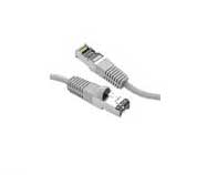
Used primarily for data transmission in local area networks (LANs), UTP network cable is a 4-pair, 100-ohm cable that consists of 4 unshielded twisted pairs surrounded by an outer jacket. Each pair is wound together for the purposes of canceling out noise that can interfere with the signal. UTP cabling systems are the most commonly deployed cable type in the U.S. |
| F/UTP (foil unshielded twisted pair) |
F/UTP cable consists of four unshielded twisted pairs surrounded by an overall foil shield. F/UTP has also been referred to as ScTP (screened twisted pair) and FTP (foiled twisted pair). F/UTP cable is not as common as UTP, but is sometimes deployed in environments where electromagnetic interference (EMI) is a significant concern. With shielded systems, the foil shield must maintain continuity throughout the entire system. |
| S/FTP (shielded foil twisted pair) |
S/FTP consists of four foil-shielded twisted pairs surrounded by an overall braided shield. This fully shielded cable is often referred to as PiMF (pairs in metal foil), or SSTP. It is the primary cable type deployed in Europe, but rarely seen in the U.S. With shielded systems, the foil shield must maintain continuity throughout the entire system. |
| Category 5 Cable |
Category 5e cable is an enhanced version of Category 5 that adheres to more stringent standards (see comparison chart below). It is capable of transmitting data at speeds of up to 1000 Mbps (1 Gigabit per second). |
> 568B Standard
Published in 2001, the TIA-568B standard sets minimum requirements for the various categories of cabling. The 568 "standard" is not to be confused with 568A or 568B wiring schemes, which are themselves part of the standard.
> 568A & 568B Wiring Schemes
When we refer to a jack or a patch panel's wiring connection, we refer to either the 568A or 568B wiring scheme, which define the pin-pair assignments for terminating UTP cable.
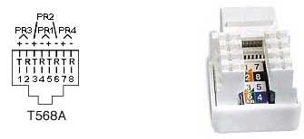
So, when someone refers to 568B, are they talking about the standard or the wiring scheme? It depends on the context. If someone were to say, "The entire office fully complies with 568B," they would be talking about the standard. If someone were to say, "The jacks and patch panels are all 568B, they would likely be referring to the wiring scheme. In UTP cable, each pair is represented by a specific color. Pair 1 is Blue, Pair 2 is Orange, Pair 3 is Green, and Pair 4 is Brown. In each pair, one wire is a solid color, and the other is predominantly white with a color stripe. When terminating UTP, each pair corresponds to a specific pin on the IDC contacts of the jack or patch panel, depending on which wiring scheme is used. The only difference between 568A and 568B is that Pairs 2 and 3 (orange and green) are swapped. The following charts illustrate the difference between the A and B methods. For those not familiar with telephony, tip (T) refers to the positive (+) side, and ring (R) refers to the negative side of the circuit.
568A Wiring
| Pair # | Wire | Pin # |
|---|---|---|
| 1 - White / Blue | White / Blue | 5 |
| Blue / White | 4 | |
| 2 - White / Orange | White / Orange | 3 |
| Orange / White | 6 | |
| 3 - White / green | White / green | 1 |
| green / White | 2 | |
| 4 - White / brown | White / brown | 7 |
| brown / white | 8 |
568B Wiring
| Pair # | Wire | Pin # |
|---|---|---|
| 1 - White / Blue | White / Blue | 5 |
| Blue / White | 4 | |
| 2 - White / Orange | White / Orange | 1 |
| Oranage / White | 2 | |
| 3 - White / Green | White / Green | 3 |
| White / Brown | 6 | |
| 4 - White / Brown | White / Brown | 7 |
| Brown / White | 8 |
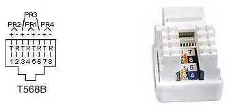
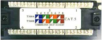
As you can see, the wiring diagrams imprinted on the jacks show both the A & B wiring methods. The back of the patch panel also shows both wiring methods, as seen below.
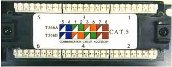
Only the Orange and Green pairs are interchanged from the A to the B method.
Its important to note that there is absolutely no difference between the two wiring schemes in terms of performance when connected from one modular device to another (jack to patch panel, RJ45 to RJ45, etc.) so long as the two devices are wired for the same scheme (pins 1 through 8 on one end are connected to pins 1 through 8 on the other end). The only time one scheme has an advantage over the other is when one end of a network link is connected to a modular device, and the other end to a punch block. In this case, the 568A wiring scheme provides a more natural progression of pairs at the punch block.
The TIA-568 standards committee decided to allow both wiring methods (568A & 568B) to exist within the 568B standard. This was done because many existing cabling plants were installed to the B standard (formerly known as WECO or AT&T 258A), and yet the standard recommends the 568A wiring scheme as the preferred method for all new installations. However, popular opinion went in the other direction, and the most popular wiring method today remains 568B. In my opinion, having both methods does nothing but cause errors and confusion. So which wiring scheme to choose? As we stated earlier; there is no difference between the two wiring schemes in connectivity or performance, so it doesnt really matter.
However, if you are terminating one end onto a punch block, the A method has the advantage. The most critical aspect is that you choose one method and stick with it. I recommend to all installers that wherever feasible, they terminate a link on both the jack and patch panel sides, and then test for proper continuity. Many times an entire installation is terminated only for the installer to then discover that the two ends of the links were wired for different methods. This requires reterminating all of the cables on one end to correct the problem.
UTP Installation Do's and Don'ts.
Run all cables in a Star Configuration so that all network links are distributed from, or homerun to, one central hub. Visualize a wagon wheel where all of the spokes start from on central point, known as the hub of the wheel.
Keep Each cable run must be kept to a maximum of 295 feet (90 meters), so that with patch cords, the entire channel is no more than 328 feet (100 meters). This is a requirement of the standard.
Keep Each cable run must be kept to a maximum of 295 feet (90 meters), so that with patch cords, the entire channel is no more than 328 feet (100 meters). This is a requirement of the standard.
Maintain the twists of the pairs as close as possible to the point of termination, or no more than 0.5"(one half inch) untwisted.
Skin off more than 1" of jacket when terminating UTP
Notes and Explanations for Do's and Don'ts
Think of a UTP network link as an extension cord to extend a network switch port to a remote location. If all of the computers and devices were located reasonably close to the switch, we would be able to connect them directly with patch cables. In most cases, this would not be practical. We therefore install cable links to remote locations from patch panels that connect the cable links to switch ports in an organized manner.
Ideally, the network link that we install should smoothly transmit data from one end to another without altering the signal transmitted from device to device in any way. Consider this fact to be Rule #1. There are many technical processes that involve transmitting data over UTP cabling. All you need to know as an installer are a few simple facts. Almost all of the dos and donts described above are specifically designed to adhere to Rule #1. The others are necessary to promote a neat, orderly, safe, and professional installation.
I strongly recommend that anyone who installs UTP cabling take the rules very seriously. An ill planned, or poorly installed cable plant, can easily become a nightmare in the future. Please also be aware that the faster the data speed, the more important the rules become. Many poorly done installations can run 10 Mbps with ease, but they may run into trouble when the network is upgraded to run higher data speeds.
Category 5, 5e, and 6 Performance Specification Chart
| Parameter | Category 5 and class D with additional requirements TSB95 and FDAM 2 | Category 5e (‘568-A-5) | Category 6 Class E (Performance at 250 MHz shown in parentheses) |
|---|---|---|---|
| Specified frequency range | 1-100 MHz | 1-100 MHz | 1-250 MHz |
| Attenuation | 24 dB | 24 dB | 21.7 dB (36 dB) |
Note: Requirements for Category 7 are currently under development.
Frequently Asked Questions
Are the cabling standards backward compatible to lower standards?
Yes. You can use a Category 6 cable to run10 Mbps Ethernet, or just for voice (phone).
I have standard Category 5 cable installed in my office. 1) Will I be able to upgrade to 100 Mbps or higher? 2) Will it help to use a higher-grade patch cable?
If the Category 5 system was properly installed, upgrading to 100 Mbps should not be a problem. Category 5 cable may even be able to run Gigabit Ethernet (1000 Mbps), however Category 5e is recommended for speeds above 100 Mbps. As for using a higher-grade patch cable, it can only help and cannot hurt. The weakest part of any network channel is typically the patch cable. I suggest that anyone responsible for a network should use the highest-grade patch cable available.
What is the difference between megabits and megahertz?
When they refer to network speed, they quantify it in megabits per second, or Mbps. This is the amount (or speed) at which data is transferred. Megahertz refers to the analog frequency of the carrier signal that is used to transmit the data. In theory, the higher the megahertz, the more megabits per second you can transmit. Higher megahertz frequencies can more easily reveal any defects in the cable or hardware, which is why proper installation is more critical for higher frequency installations.
I just bought some UTP cable and jacks plus a LAN-PRO-8 Toolkit from you guys, and I want to install new cable runs, connecting them to an existing patch panel in our office. The patch panel is not marked 568A or 568B. How can I tell what it actually is wired for?
Take a piece of UTP cable, about a foot or so. Connect a jack on one end using the 568B wiring scheme. Connect the other end to the patch panel in the standard fashion (blue, orange, green, brown). Test the cable from jack to patch panel with the LANTEST-PRO Cable Tester cable tester. If the test passes, the patch panel is 568B. If not, reterminate the jack using the 568A wiring scheme and retest. If it tests ok, the patch panel is 568A. Once you determine if it is A or B, all of the new jacks should be wired to that standard.
I am trying to troubleshoot a UTP jack that worked fine until recently, but now suddenly it doesn't seem to work. I disconnected the switch/hub and the computer, tested out the cable, and it tests ok. I took the computer to another location, and it worked fine. What could be the problem?
If the above remedies do not help, I would recommend tracing the line for its entire length, looking for signs of, and correcting any, EMI interference, kinks, poor termination methods, cable ties installed too tightly, etc. Then change the jack and patch panel port. If that doesn't work, you could call in a professional to do further testing, but it would probably be quicker and cheaper just to install a new link.
We have a 100 Mbps Ethernet network that is cabled with Category 5 in our office. We need to get a group of computers onto the network that are located on the other side of our warehouse, about 600 feet away. I understand that UTP cable links are limited to a distance of 295 feet. What is the best way to accomplish this?
You can run a fiber optic cable and connect it to your existing copper switch with a Media Converter. Measure the exact distance of the cable run. Let us know the distance, and we will make a fiberoptic cable for you, complete with connectors and a pulling eye to protect the connections during installation. Use a 100Base- TX to FX media converter on each end. On the far end, you can install a new switch/hub off of the Media Converter to connect to all of the users.
What is plenum and PVC cable, and why is the plenum cable so much more expensive?
Plenum-rated cable has a special insulation that has low-smoke and low-flame characteristics. Plenum cable is mandated to be installed in any "air handling" space. For example, most large office buildings use the ceiling to return air to the AC unit. This qualifies the ceiling space and a plenum space, and all cable that go through that ceiling must be plenum rated. Please check with your building officials to see if you need plenum cable. Plenum cable costs more because the material required for the insulation is more expensive.
Is the order of the colors really that critical in a patch cable? As long as both ends of a straight through cable match, won't the cable work well regardless of the color order?
Of course the signals that travel over those wire pairs are color blind. They could care less (if they could think) what color is on their insulation. However, the pairs are grouped inside of the cable and in the RJ-45 connector in a certain fashion so each pair will react with each other in a unique way. This reaction does have an effect on the performance. The more important factor is the pairing. A transmit and receive circuit must travel over one pair that is twisted for maximum shielding from crosstalk.
I am planning a cabling installation in a large building. How can we keep all of the cable runs within the distance limitation of 295 feet?
This question may require an entire article to properly cover. Basically, you should strategically divide the building into sections. Pick a central location (equipment closet) for each section that allows all of the cable runs in that section to fall within 295 feet. Now choose a main equipment location. You now need to plan a backbone cable from the main equipment room to connect each switch/hub in each closet to the main switch. If the distance of the closet to the main equipment room is within 295 feet, you may run a UTP backbone to that closet. However, if the run is over 295 feet, a fiber optic backbone is required. A fiber optic backbone is also necessary if you need higher speeds to transmit a lot of data from many locations. Be sure to use switch ports to link to the main switch to assure that data can effectively be transmitted without having to share bandwidth. If only a few runs fall over the 295 feet, and you dont need higher bandwidth in the backbone, you may want to consider using media converters.
In Closing
We hope that you have found this article helpful. I realize that this type of project can seem rather complicated to someone who has never done it before. The truth is that it is really very simple. If you follow the rules and suggestions presented in this article, you should not have any problems. We here at LANshack.com sell just about everything you will need to do an installation. We hope that you will consider us when purchasing your supplies.