 Free shipping on orders over $250 Use code SHIP4FREE
 888-568-1230
Fast Lead Times | Fast Shipping


- Pre-Terminated Fiber Optic Assemblies
- back
- In Stock Pre-Terminated
- Indoor Plenum
- Indoor / Outdoor
- Indoor Plenum Interlock Armor
- Indoor Ultra Thin Armored
- I/O Plenum Interlock Armor
- Indoor / Outdoor Ultra Thin Armored
- Outdoor SST Drop Self Supporting
- Outdoor Loose Tube (OSP)
- Outdoor Gel Filled (OSP)
- Outdoor Ultra Thin Armored (OSP)
- Outdoor Armored Direct Burial (OSP)
- Outdoor Aerial with Messenger (OSP)
- Tactical and Rugged Deployable
- back
- Multimode OM3 Tactical
- Multimode OM4 Tactical
- Singlemode Tactical
- OpticalCON Tactical
- back
- 2 Fiber OM3 - Broadcast Tactical
- 2 Fiber SM - Broadcast Tactical
- 4 Fiber OM3 - Broadcast Tactical
- 4 Fiber SM - Broadcast Tactical
- 12 Fiber OM3 - Broadcast Tactical
- 12 Fiber SM - Broadcast Tactical
- DUO Chassis Connector
- Neutrik D-Series Patch Panel
- DUO SM Inline Coupler
- DUO OM3 Inline Coupler
- DUO APC Inline Coupler
- OpticalCON MTP 12 Chassis Connector
- 2 Port D-Series Wall Plate
- 1 Port D-Series Wall Plate
- HMA Expanded Beam Tactical
- back
- 2 Channel/Fiber
- 4 Channel/Fiber
- Ex. Beam 2 CH/F MM OM3 Chassis Conn.
- Ex. Beam 4 CH/F MM OM3 Chassis Conn.
- 4 CH to 2 X 2 CH OM3 Ex. Beam
- 2 CH OM3 Ex. Beam to OpticalCON Duo
- 4 CH OM3 Ex. Beam to OpticalCON Quad
- 4 CH OM3 Ex. Beam to 2 x OpticalCON Duo
- Ex. Beam Color Coding Ring
- 1 Port D-Series Wall Plate
- 2 Port D-Series Wall Plate
- Ex. Beam 1 CH/F MM OM3 Rotary Joint
- Ex. Beam 2 CH/F MM OM3 Conn. Mod.
- Ex. Beam 4 CH/F MM OM3 Conn. Mod.
- Mil-Tac Tactical Assemblies
- Neutrik® OpticalCON®
- back
- OpticalCON DUO
- back
- 2 Fiber SM - Broadcast Tactical
- 2 Channel SM - Mil-Tac Extreme
- 2 Fiber SM Hybrid SMPTE
- 2 Fiber OM3 - Broadcast Tactical
- 2 Fiber OM3 - Mil-Tac Extreme
- 2 Fiber SM - Tactical Patch Cable
- 2 Fiber OM3 - Tactical Patch Cable
- SM Duo to 2 Simplex Breakout Assembly
- OM3 Duo to 2 Simplex Breakout Assembly
- DUO Chassis Connector
- DUO Chassis Connector
- Neutrik D-Series Patch Panel
- DUO OM3 Inline Coupler
- DUO SM Inline Coupler
- DUO APC Inline Coupler
- 1 Port D-Series Wall Plate
- OpticalCON QUAD
- back
- 4 Fiber SM - Broadcast Tactical
- 4 Fiber SM - Mil-Tac Extreme
- 4 Fiber OM3 - Broadcast Tactical
- 4 Fiber OM3 - Mil-Tac Extreme
- 4 Channel SM Lite Tac Patch
- 4 Fiber OM3 - Tac Patch Cable
- SM Quad to 4 Simplex Breakout Assembly
- OM3 Quad to 4 Simplex Breakout Assembly
- QUAD Chassis Connector
- Neutrik D-Series Patch Panel
- QUAD OM3 Inline Coupler
- QUAD SM Inline Coupler
- QUAD APC Inline Coupler
- SHUTTER BUDDY
- 1 Port D-Series Wall Plate
- 2 Port D-Series Wall Plate
- OpticalCON MTP
- back
- 12 Fiber SM - Broadcast Tactical
- 12 Fiber SM - Mil-Tac Extreme
- 12 Fiber OM3 - Broadcast Tactical
- 12 Fiber OM3 - Mil-Tac Extreme
- 12 Channel MTP SM Lite Tac Patch
- 12 Fiber OM3 - Tac Patch Cable
- SM MTP to 12 Simplex B/O Assembly
- OM3 MTP to 12 Simplex B/O Assembly
- OpticalCON MTP 12 Chassis Connector
- Neutrik D-Series Patch Panel
- OM3 Multimode Inline Coupler
- Singlemode APC Inline Coupler
- 1 Port D-Series Wall Plate
- 2 Port D-Series Wall Plate
- Hybrid Fiber + Power
- MTP Trunk Cables, Fanouts, & Cassettes
- back
- Indoor MTP Trunks
- Indoor/Outdoor MTP Trunks
- Indoor Armored MTP Trunks
- In/Outdoor Armored MTP Trunks
- Outdoor Loose Tube MTP Trunks
- Outdoor Self Sup. Drop MTP Trunks
- Outdoor Micro Armored MTP Trunks
- Outdoor Armored MTP Trunks
- IP68 Weatherproof OptiTip® HMFOC
- Stock Indoor MPO Cables
- Stock In/Outdoor MTP/MPO Trunks
- Indoor MTP Fanouts
- back
- Multimode OM3 50/125
- back
- 1 x 12 MTP to 12 Simplex Connectors
- 2 x 12 MTP to 24 Simplex Connectors
- 4 x 12 MTP to 48 Simplex Connectors
- 6 x 12 MTP to 72 Simplex Connectors
- 8 x 12 MTP to 96 Simplex Connectors
- 12 x 12 MTP to 144 Simplex Connectors
- 1 x 24 MTP to 24 Simplex Connectors
- 2 x 24 MTP to 48 Simplex Connectors
- 3 x 24 MTP to 72 Simplex Connectors
- 4 x 24 MTP to 96 Simplex Connectors
- 6 x 24 MTP to 144 Simplex Connectors
- Multimode OM4 50/125
- back
- 1 x 12 MTP to 12 Simplex Connectors
- 2 x 12 MTP to 24 Simplex Connectors
- 4 x 12 MTP to 48 Simplex Connectors
- 6 x 12 MTP to 72 Simplex Connectors
- 8 x 12 MTP to 96 Simplex Connectors
- 12 x 12 MTP to 144 Simplex Connectors
- 1 x 24 MTP to 24 Simplex Connectors
- 2 x 24 MTP to 48 Simplex Connectors
- 3 x 24 MTP to 72 Simplex Connectors
- 4 x 24 MTP to 96 Simplex Connectors
- 6 x 24 MTP to 144 Simplex Connectors
- Singlemode 9/125
- back
- 1 x 12 MTP to 12 Simplex Connectors
- 2 x 12 MTP to 24 Simplex Connectors
- 4 x 12 MTP to 48 Simplex Connectors
- 6 x 12 MTP to 72 Simplex Connectors
- 8 x 12 MTP to 96 Simplex Connectors
- 12 x 12 MTP to 144 Simplex Connectors
- 1 x 24 MTP to 24 Simplex Connectors
- 2 x 24 MTP to 48 Simplex Connectors
- 3 x 24 MTP to 72 Simplex Connectors
- 4 x 24 MTP to 96 Simplex Connectors
- 6 x 24 MTP to 144 Simplex Connectors
- 2 x 12 MTP to 24 Simplex Connectors
- 4 x 12 MTP to 48 Simplex Connectors
- Indoor / Outdoor MTP Fanouts
- MTP OSP Loose Tube Fanout Cable
- MTP OSP Armored Fanout Cable
- Stock Indoor MPO Fanout Cables
- Cassettes and Components
- back
- OM3 Cassettes
- OM4 Cassettes
- Singlemode Cassettes
- Enclosures
- back
- Super High Density 5 panel (1U)
- Super High Density 14 panel (2U)
- Lightweight Aluminum 2 panel (1U)
- Lightweight Aluminum 3 panel (1U)
- Lightweight Aluminum 4 panel (2U)
- Lightweight Aluminum 6 panel (2U)
- Lightweight Aluminum 12 panel (4U)
- Multilink 2 Panel (1U)
- Multilink 3 panel (1U)
- Multilink 4 panel (2U)
- Multilink 6 panel (2U)
- Multilink 12 panel (2U)
- 4 panel (1U) UHD Patch Panel
- Couplers and Adapter Panels
- MTP/MPO to LC LGX Cable Harness
- Fiber Patch Cables, Enclosures, & Couplers
- back
- Fiber Enclosures & Adapter Panels
- back
- Rack Mount Termination Boxes
- back
- Lightweight Aluminum 2 panel (1U)
- Multilink 2 Panel (1U)
- 2 panel (1U) Slide Out 16 AWG
- Lightweight Aluminum 3 panel (1U)
- 3 panel (1U) Swing Out Splice Box
- 3 panel (1U) LGX Patch Panel
- Multilink 3 panel (1U)
- 3 panel (1U) Slide Out 16 AWG
- 4 panel (1U) UHD Patch Panel
- Lightweight Aluminum 4 panel (2U)
- Multilink 4 panel (2U)
- Lightweight Aluminum 6 panel (2U)
- Multilink 6 panel (2U)
- Lightweight Aluminum 12 panel (4U)
- Multilink 12 panel (2U)
- Super High Density 5 panel (1U)
- Wall Mount Termination Boxes
- back
- QuickTreX 2 Adapter / 1-4 Fiber
- Lightweight Aluminum 1 panel
- Heavy Duty Steel 1 panel
- Multilink 1 Panel
- Multilink 1 Panel w/ Splice
- Lightweight Aluminum 2 panel
- Multilink 2 Panel
- Lightweight Aluminum 4 panel
- Multilink 4 Panel
- Multilink 4 Panel with Splice
- QuickTreX 2 Adapter / 1-4 Fiber
- QuickTreX 8 Adapter / 1-16 Fiber
- Outdoor Harsh Environment
- back
- QuickTreX 1 Adapter / 1-2 Fiber
- QuickTreX 2 Adapter / 1-4 Fiber
- QuickTreX 8 Adapter / 1-16 Fiber
- QuickTreX 16 Adapter w/Splice - IP65
- QuickTreX 6 Panel Steel w/Splice
- QuickTreX 24 Adapter w/Splice - IP65
- QuickTreX 1 Panel Splitter/Splice Enclosure
- Multilink 2 Panel Outdoor
- QuickTreX 1-36F Aerial/Wall Splice/Splitter Box
- QuickTreX 144 Fiber Aerial Splice Enclosure
- QuickTreX 480 Splice Dome Enclosure
- QuickTreX 12 Fiber Splice
- 4 panel Outdoor NEMA Enclosure
- Dome Pedestal Enclosure
- Multimode OM1 Adapter Panels
- Multimode OM2/3/4 Adapter Panels
- Multimode OM5 Adapter Panels
- Singlemode Adapter Panels
- back
- QuickTreX 12 Fiber LC UPC
- QuickTreX 12 Fiber LC APC
- Multilink 12 Fiber LC UPC
- Multilink 12 Fiber LC APC
- QuickTreX 24 Fiber LC UPC
- QuickTreX 24 Fiber LC APC
- Multilink 24 Fiber LC UPC
- Multilink 24 Fiber LC APC
- QuickTreX 6 Fiber SC UPC
- QuickTreX 6 SC APC
- QuickTreX 12 Fiber SC UPC
- QuickTreX 12 Fiber SC APC
- Multilink 6 Fiber SC UPC
- Multilink 6 Fiber SC APC
- Multilink 12 SC UPC
- Multilink 12 SC APC
- MTP Adapter Panels
- Blank Adapter Panels
- Splice Trays
- Custom Fiber Optic Patch Cables
- Custom Armored Fiber Patch Cables
- Stock Tactical Fiber Patch Cables
- back
- Stock Tac SM - Duplex LC UPC - 100FT
- Stock Tac SM - Duplex LC APC - 100FT
- Stock Tac SM - Duplex SC APC - 100FT
- Stock Tac SM - Duplex SC UPC - 100FT
- Stock Tac SM - Simplex LC UPC - 100FT
- Stock Tac SM - Simplex SC UPC - 100FT
- Stock Tac SM - Simplex SC APC - 100FT
- Stock Tac SM - Simplex LC APC - 100FT
- Stock Duplex Fiber Patch Cables
- Stock Uniboot Fiber Patch Cables
- Stock Simplex Fiber Patch Cables
- Fiber Optic Couplers & Attenuators
- back
- Multimode OM1 62.5/125
- back
- LC Simplex w/ Flange
- LC Duplex w/ Flange
- SC Simplex w/o Flange
- SC Simplex w/ Flange
- SC Simplex w/ Flange and Hinged Door
- LC Quad w/ Flange
- SC Duplex w/ Flange
- ST Simplex - Universal MM/SM w/o Flange
- FC Simplex - Universal MM/SM w/o Flange
- ST Simplex - Universal MM/SM w/Flange
- ST Duplex - Universal MM/SM w/Flange
- Multimode OM3/4 50/125
- back
- LC Duplex w/ Flange
- LC Quad w/o Flange
- LC Quad w/ Flange
- SC Simplex w/o Flange
- SC Simplex w/ Flange
- SC Duplex w/ Flange
- ST Simplex - Universal MM/SM w/o Flange
- FC Simplex - Universal MM/SM w/o Flange
- ST Simplex - Universal MM/SM w/Flange
- MPO Coupler - MM OM3 / OM4 Aqua
- ST Duplex - Universal MM/SM w/Flange
- Multimode OM5 50/125
- Singlemode
- back
- LC UPC Simplex w/o Flange
- LC APC Simplex w/o Flange
- LC UPC Duplex w/ Flange
- LC APC Duplex w/ Flange
- LC UPC Quad w/o Flange
- LC APC Quad w/o Flange
- SC UPC Simplex w/ Flange
- SC UPC Simplex w/o Flange
- SC UPC Simplex w/ Flange and Hinged Door
- SC APC Simplex w/ Flange
- SC APC Simplex w/o Flange
- SC APC Simplex w/ Flange and Hinged Door
- SC UPC Duplex w/ Flange
- SC APC Duplex w/ Flange
- ST Simplex - Universal MM/SM w/Flange
- ST Simplex - Universal MM/SM w/o Flange
- Keystone Couplers & Accessories
- back
- LC Duplex MM OM1 - Ivory
- LC Duplex MM OM3 / 4 - Aqua
- LC Duplex MM OM5 - Lime Green
- LC UPC Duplex SM - Blue
- LC Duplex SM APC - Green
- SC Simplex MM OM1 - Beige
- SC Simplex MM OM3 / 4 - Aqua
- SC UPC Simplex SM - Blue
- SC APC Simplex SM - Green
- MTP Singlemode
- MTP Multimode OM3/4
- Gloss Finish Keystone Wallplates
- Easy Wallplate Bracket
- 12 Port - 1U
- 6 Port LGX Blank Keystone Adapter Panel
- MTP / MPO Couplers
- Optical Attenuators
- Fiber Optic Splitters
- Mode Conditioning Fiber Cables
- Bulk Fiber Optic Cable, Testing, & Cleaning
- back
- Unterminated Fiber Optic Cable
- Fiber Optic Pigtail Kits
- back
- OM1 62.5/125 Multimode
- OM3 50/125 Multimode
- OM4 50/125 Multimode
- OM5 50/125 Multimode
- Singlemode
- back
- 1 meter LC 6 Fiber
- 3 meter LC 6 Fiber
- 3 meter SC 6 Fiber
- 1 meter ST 6 Fiber
- 3 meter ST 6 Fiber
- 1 meter LC 12 Fiber
- 3 meter LC 12 Fiber
- 3 meter LC APC
- 3 meter LC 12 Fiber Ribbon
- 3 meter SC APC 12 Fiber
- 3 meter SC 12 Fiber
- 3 meter SC UPC 12 Fiber Ribbon
- 1 meter ST 12 Fiber
- 3 meter ST 12 Fiber
- 2 meter LC 1 Fiber
- 2 meter SC 1 Fiber
- Fiber Optic Splice Trays & Boxes
- back
- Fiber Optic Splice Enclosures
- back
- Multilink 2 Panel Outdoor
- QuickTreX 8 Adapter / 1-16 Fiber
- QuickTreX 16 Adapter w/Splice - IP65
- QuickTreX 480 Splice Dome Enclosure
- QuickTreX 144 Fiber Aerial Splice Enclosure
- QuickTreX 24 Adapter w/Splice - IP65
- QuickTreX 6 Panel Steel w/Splice
- QuickTreX 1 Panel Splitter/Splice Enclosure
- Multilink 1 Panel w/ Splice
- Multilink 4 Panel with Splice
- Lightweight Aluminum 1 panel
- 3 panel (1U) Swing Out Splice Box
- QuickTreX 12 Fiber Splice
- Fiber Optic Splice Trays
- Fiber Optic Supplies & Tools
- Fiber Optic Cleaning Products
- Fiber Optic Test Instruments
- Fusion Splicers and Accessories
- Fiber Optic Loopback Testers
- Fiber Optic Mounting Hardware
- Fiber Optic Reference Cable Kits
- Ethernet Patch Cables, Bulk Cable, & Accs.
- back
- Ethernet Patch Cables
- back
- Tactical & Rugged Deployable
- back
- Cat 5E Shielded - Custom Length
- Stock 40FT Cat 5E Shielded
- Cat 6A Shielded - Custom Length
- Stock 30FT Cat 6A Shielded
- RJ45 etherCON Coupler
- RJ45 etherCON Coupler w/ Sealing Kit
- RJ45 Cat 6A etherCON Coupler - Black
- Cat 6A etherCON Coupler - Nickel
- Neutrik D-Series Patch Panel
- Cat 6 Outdoor Inline
- Cat 6A Outdoor Panel Mount w/Cap
- Cat 6A Outdoor Panel Mount
- Cat 6 Outdoor Panel Mount
- Cat 6 Outdoor Panel Mount w/Cap
- Outdoor Patch Cable Cap
- Cat 5E Custom Made in the USA
- Cat 5E Stock
- Cat 6E Custom Made in the USA
- Cat 6 Stock
- Cat 6A Custom Made in the USA
- Cat 6A Stock
- Cat 6A Stock Outdoor Armored
- Stock Cat 6A Shielded Tactical
- Outdoor Custom Made in the USA
- Cat 6 Outdoor
- Cat 8 Custom Made in the USA
- Cat 7 Stock
- Cat 8 Stock
- 110 Cat 5 Custom Patch Cables
- Custom Cable Bundles
- Bulk Ethernet Cable
- back
- Cat 5e Unshielded
- back
- PVC, (CM), Stranded, 1000ft
- PVC, Riser (CMR), Solid, 1000 ft
- 24AWG Solid Riser , 1000 ft
- Plenum Rated Solid 1000FT USA Made
- Solid Plenum 1000FT
- 24AWG Solid Plenum, 1000 ft
- Direct Bury, CMX, Solid, 1000 ft
- 24 AWG Direct Burial Solid, 1000 ft
- 24 AWG Outdoor DB 1000FT USA Made
- Cable Reel Deployment Caddy
- Cat 5E Shielded
- Cat 6 / 6e Unshielded
- back
- PVC, (CM), Stranded, 1000ft
- PVC, 28 AWG Stranded, 1000 ft
- PVC Riser (CMR), Solid, 1000 ft
- 23AWG Solid Riser (CMR), 1000 ft
- Plenum (CMP), Solid, 1000 ft
- 23AWG Solid Plenum (CMP), 1000 ft
- Outdoor DB Solid 1000FT USA Made
- Direct Burial, CMX, Solid, 1000 ft
- Outdoor w/Messenger 1000FT USA Made
- Cable Reel Deployment Caddy
- Cat 6 / 6E Shielded Bulk Cable
- Cat 6A Unshielded
- Cat 6A Shielded
- Cat 7A Shielded
- Cat 8 Shielded
- Data & Voice Connectors
- back
- Keystone Jacks
- back
- Cat 5E - 90° Punch Down
- Cat 5E - 180°Punch Down
- Cat 6 - 90° Punch Down
- Cat 6 - 180° Punch Down
- Cat 6 Shielded 90° Punch Down
- Cat 6A - 90° Punch Down
- Cat 6A Shielded 90 Degree
- Cat 6A Shielded -180° Toolless
- Cat 8 Shielded - 90° Toolless
- Cat 8 Shielded - 90° Toolless w/Door
- RJ-11/12 Voice - 90° Punch Down
- Keystone Couplers
- Modular Plugs
- back
- Cat 5E UTP - 100 pcs USA Made
- Cat 6/6E UTP - 100 pcs USA Made
- Cat 5E/6E STP - 50 pcs USA Made
- Cat 5E/6E STP - 10 pcs USA Made
- Cat 6A STP - 50 pcs USA Made
- Cat 6A STP - 10 pcs USA Made
- Cat 8 STP - 10 pcs
- Cat 8 STP - 25 pcs
- Cat 8 STP Toolless
- Cat 6A UTP - 100 pcs
- Cat6 UTP Feed Through - 100 pcs
- Cat 6 STP Feed Through - 100 pcs
- Strain Relief Boots
- Wallplates and Surface Mount Boxes
- Splitters
- Coaxial F Connectors
- Ethernet Patch Panels
- Datacom Tools and Testers
- back
- Data & Voice Tools
- back
- PRO RJ-45 Crimper
- PRO Large OD Crimper
- Hex Crimper
- Economy RJ-45 Crimper
- PRO 110 Impact Termination Tool
- 110 Replacement Blade
- 66 Replacement Blade
- EZ RJ45 Keystone Jack Crimper
- Economy Termination Tool
- Wire and Kevlar Scissors
- Large OD Cable Stripper & Cutter
- UTP & STP Cable Stripper
- Electrical Wire Stipper
- Coaxial Cable Cutter
- Conductor Separator & Straightener
- QuickTreX Premium Adjustable Hat
- Test Equipment
- Cable Installation
- Coaxial CATV Tools
- Hand Tools
- Cable Reels
- Bulk Coaxial, Audio, and Power Cable
- back
- Co-ax RG-6 Shielded Bulk Cable
- back
- Dual Shield CCS Riser, 1000 ft WT
- Quad Shield CCS Riser, 500 ft BK
- Quad Shield CCS Riser, 1000 ft BK
- Quad Shield CCS Plenum, 1000 ft WT
- Quad Shield Solid Copper Plenum, 1000
- Dual Shield Direct Burial CCS, 1000 ft BK
- Quad Shield Direct Burial CCS, 1000 ft BK
- RG6 F Male Compression 10 Pack
- Cable Reel Deployment Caddy
- Composite Cable & Cable Bundles
- Power Cable Bulk
- Thermostat Bulk Cable
- back
- 18/2 Riser Rated, Solid Copper PVC, 500 ft
- 18/3 Riser Rated, Solid Copper PVC, 500 ft
- 18/4 Riser Rated, Solid Copper PVC, 500 ft
- 18/5 Riser Rated, Solid Copper PVC, 500 ft
- 18/6 Riser Rated, Solid Copper PVC, 500 ft
- 18/8 Riser Rated, Solid Copper PVC, 500 ft
- 20/2 Riser Rated, Solid Copper PVC, 500 ft
- 20/5 Riser Rated, Solid Copper PVC, 500 ft
- 20/8 Riser Rated, Solid Copper PVC, 500 ft
- Cable Reel Deployment Caddy
- Audio Cable Bulk
- IT Technician Tool Kits and Cases
- RJ45 Dust Plugs, Caps, and Locks
- Cable Mounting Hardware
- HDMI Cables
- Power Cords and Supplies
- Harsh Environment Cables, FTTA, RF, & IP68
- back
- OptiTip, OptiTap, HMA, & FTTA
- RF Cable Assemblies
- RF Connectors & Adapters
- back
- RF Connectors
- back
- Mini-UHF Male Crimp
- Mini-UHF Male Crimp RG-58/U
- UHF Male Solder
- UHF Male Crimp
- M Male Crimp
- N Male Crimp 50 ohm
- N Male Crimp G,G,T, 50 ohm
- N Male Crimp For Cable Group X S,G,T
- N Male Crimp RG-142/U & RG-55/U
- N Male Crimp for Cable Group B N,G,T
- SMA Male Crimp
- SMA Male Crimp RG-8/X
- SMA Male Crimp for Cable Group B N,G,T
- BNC Male Crimp RG58/U
- TNC Male Crimp RG-58/U
- TNC Male Crimp RG-8X
- RF Adapters
- Harsh Env. Fiber Optic Assemblies
- Toolkits, Cases & Enclosures
- back
- Termination Boxes
- back
- Multilink 2 Panel Outdoor
- 4 panel Outdoor NEMA Enclosure
- Dome Pedestal Enclosure
- QuickTreX 2 Adapter / 1-4 Fiber
- QuickTreX 8 Adapter / 1-16 Fiber
- QuickTreX 16 Adapter w/Splice - IP65
- QuickTreX 6 Panel Steel w/Splice
- QuickTreX 24 Adapter w/Splice - IP65
- QuickTreX 1 Panel Splitter/Splice Enclosure
- QuickTreX 1-36F Aerial/Wall Splice/Splitter Box
- QuickTreX 144 Fiber Aerial Splice Enclosure
- QuickTreX 480 Splice Dome Enclosure
- Network IT Toolkits
- Network IT Tool Cases
- Ethernet Patch Cables & Bulk Cable
- back
- Copper Cables and Assemblies
- Bulk Outdoor Copper Cable
- Outdoor Patch Cables
- Outdoor Accessories
- back
- Cat 6 Outdoor Panel Mount
- Cat 6 Outdoor Panel Mount w/Cap
- Cat 6 Shielded Outdoor Panel Mount
- Cat 6 Shielded Outdoor Panel Mount w/Cap
- Outdoor Patch Cable Cap
- 1 Gang Outdoor Wallplate
- Water-Resistant 1 Gang
- 1 Port (1 Gang) Stainless Steel Keystone Wall Plate for Mounting RJ45 Keystone Connectors and Couplers
- Network Switches, SFPs, Converters, & Racks
- back
- Network Switches
- back
- Unmanaged Gigabit
- Managed Gigabit
- Unmanaged Gigabit PoE
- back
- QuickTreX 8 Port GIG w/ 4xRJ45,1xRJ,1xSFP
- QuickTreX 12 Port GIG w/ 8xRJ45,2xRJUL,2xSFP
- QuickTreX 24 Port GIG w/ 24xRJ45 & 2xSFP
- QuickTreX 48 Port GIG w/ 48xRJ45 & 2xSFP
- 8 Port Gigabit w/ 2 Gigabit SFP Ports
- 16 Port Gigabit w/ 2 Gigabit SFP Ports
- 24 Port Gigabit w/ 2 Gigabit SFP Ports
- 4 Port Gigabit
- Managed Gigabit PoE
- back
- QuickTreX 8 Port GIG w/ 8xRJ45 & 2xSFP
- QuickTreX 24 Port GIG w/ 24xRJ45 & 4xSFP/RJ45
- QuickTreX 36 Port 10G UL w/ 24xRJ45, 8xSFP, 4xSFP+
- 8 Port Gigabit w/ 2 Gigabit SFP Ports
- 24 Port Gigabit w/ 2 Gigabit SFP Ports
- 24 Port G w/ 4 x GIG SFP Ports + PoE Inj
- 24 Port Gigabit w/ 4 x 10Gigabit SFP Ports
- 24 Port Gigabit w/ 2 SFP Ports (Full Power)
- 24 Port Gigabit w/ 4 SFP+ Ports (Full Power)
- Unmanaged Industrial Switches
- Managed Industrial Switches
- Unmanaged Industrial PoE Switches
- back
- QuickTreX 6 Port GIG w/ 4xRJ45 & 2xSFP
- QuickTreX 10 Port GIG w/ 8xRJ45 & 2xSFP
- 4 Port Gigabit POE+ w/ 2 SFP Ports
- 4x10/100M TX PSE and 1x1000M SC MM
- 4x10/100M TX PSE + 1x10/100M
- 5 x RJ45 10/100/100BaseTX
- 5 x RJ45 1000Bast w/ 4 x Gig 30W PSE
- 8 x RJ45 10/100/1000m w/ v Boost
- 8 Port Gigabit POE+ w/ 2 SFP Ports
- 8 x Gig TX 30W PSE + 2 x 1000M TX/SFP w/ v Boost
- Managed Industrial PoE Switches
- Industrial Power Supplies
- SFP / QSFP Modules
- back
- Multimode SFP Modules
- Singlemode SFP Modules
- back
- 1.25 GIG - 2km at 1310nm by QuickTreX
- 10 GIG - 10km at 1310nm by QuickTreX
- 1F/BiDi Kit 1.25 GIG - 20km by QuickTreX
- 1.25 GIG - 20km at 1310nm by Unicom
- 1.25 GIG - 40km at 1310nm by Unicom
- 1.25 GIG - 80km at 1310nm by Unicom
- 1.25 GIG - 100km at 1310nm by Unicom
- 1.25 GIG - 120km at 1310nm by Unicom
- 1.25 GIG - 160km at 1310nm by Unicom
- 1.25 GIG - 180km at 1310nm by Unicom
- 10 GIG - 10km at 1310nm by Unicom
- 10 GIG - 40km at 1550nm by Unicom
- 10 GIG - 80km at 1550nm by Unicom
- 10 GIG - 100km at 1550nm by Unicom
- 10 GIG - 10km at 1310nm Cisco Compatible
- 1.25 GIG - 10km at 1310nm by Signamax
- Industrial SFP Modules
- back
- MM 1.25 GIG - 500 m / 850nm by QuickTreX
- SM 1.25 GIG - 20 km / 1310nm by QuickTreX
- MM 10 GIG - 300m / 850nm by QuickTreX
- SM 10 GIG - 10 km / 1310nm by QuickTreX
- MM GIG - 550m / 850nm by Signamax
- MM GIG - 2km / 1310nm by Signamax
- SM GIG - 10km / 1310nm by Signamax
- SM GIG - 40km / 1310nm by Signamax
- SM GIG - 40km / 1550nm by Signamax
- SM GIG - 80km / 1550nm by Signamax
- SM GIG - 110km / 1550nm by Signamax
- SM BiDI GIG - 10km 1310TX/1550RX
- SM BiDI GIG - 10km 1550TX/1310RX
- QSFP Modules
- Media Converters
- Network Racks and Cabinets
- back
- Free Standing Racks
- Open Frame Wall Rack
- back
- QuickTreX 16U (19"W x 18"D)
- Kendall Howard 8U (Adjustable W x 18"D)
- Kendall Howard 12U (Adjustable W x 18"D)
- Kendall Howard 12U Swing-Out
- Kendall Howard 18U Swing-Out
- Kendall Howard 12U Side Load
- Kendall Howard 12U (19"W x 12"D)
- Kendall Howard 16U (19"W x 12"D)
- Kendall Howard 12U (19"W x 18"D)
- Kendall Howard 16U (19"W x 18"D)
- Kendall Howard 2U Vertical w/ Tapped Rails
- Kendall Howard 4U Vertical w/ Tapped Rails
- Kendall Howard 2U Vertical
- Kendall Howard 4U Vertical
- Wall Mount Network Cabinets
- back
- QuickTreX 4U Swing-Out Hinged
- QuickTreX 4U Fixed
- QuickTreX 6U Swing-Out Hinged
- QuickTreX 6U Fixed
- QuickTreX 9U Swing-Out Hinged
- QuickTreX 9U Fixed
- QuickTreX 12U Fixed
- 6U Wall Mount - Glass Door
- 6U Wall Mount - Solid Door
- 6U Wall Mount - Vented Door
- 6U Swing Out Wall Mount - Glass Door
- 6U Swing Out Wall Mount - Solid Door
- 6U Swing Out Wall Mount - Vented Door
- 9U Wall Mount - Glass Door
- 9U Wall Mount - Vented Door
- 9U Wall Mount - Solid Door
- Network Rack & Cabinet Shelves
- Hardware, Fans, and Accessories
- Rack Mount Cable Management Panels
- Wireless Access Points
- Cable Wraps, Straps, and Ties
- back
- Pre-Cut Hook & Loop Velcro Cable Ties
- back
- 6" x 1/2" Velcro Cable Ties - 25 pcs
- 6" x 1/2" Velcro Cable Ties - 100 pcs
- 6" x 1/2" Velcro Cable Ties - 1200 pcs
- 8" x 1/2" Velcro Cable Ties - 25 pcs
- 8" x 1/2" Velcro Cable Ties - 100 pcs
- 8" x 1/2" Velcro Cable Ties - 900 pcs
- 12" x 1/2" Velcro Cable Ties - 25 pcs
- 12" x 1/2" Velcro Cable Ties - 100 pcs
- 12" x 1/2" Velcro Cable Ties - 600 pcs
- 18" x 1/2" Velcro Cable Ties - 25 pcs
- 18" x 1/2" Velcro Cable Ties - 100 pcs
- 18" x 1/2" Velcro Cable Ties - 400 pcs
- Bulk Roll Velcro Cable Strap
- Wall Mount Velcro Cable Straps
- Fire Retardant Hook & Loop Cable Ties
- back
- 8" x 1/2" Velcro Hook & Loop Ties - 10 pcs
- 8" x 1/2" Velcro Hook & Loop Ties - 100 pcs
- 8" x 1/2" Velcro Ties - 900 pcs
- 12" x 1/2" Velcro Hook & Loop Ties - 100 pcs
- 12" x 1/2" Velcro Hook & Loop Ties - 600 pcs
- 18" x 1/2" Velcro Hook & Loop Ties - 10 pcs
- 18" x 1/2" Velcro Hook & Loop Ties - 400 pcs
- 75 Ft x 1/2" Roll Velcro Cable Wrap Strap
- Economy Velcro Cable Ties
- Cable Bundle Socks
- Clip-On Velcro Cable Carrier
- TV & LCD Screen Mounts
- back
- Wall Mount TV/LCD Screen Mounts
- back
- 13" - 27" Screen w/ 10.4" Arm
- 13" - 42" Screen w/ 10.7" Arm
- 10" - 42" Screen w/ 7.5" Arm
- 10" - 42" Screen w/ 2.9" Arm
- 13" - 42" Screen w/ 14.3" Arm
- 26" - 47" Screen w/ 22.8" Arm
- 32" - 70" Screen w/ 18.4" Arm
- 37" - 80" Screen w/ 18.4" Arm
- 32" - 55" Screen
- 37" - 70" Screen
- 37" - 80" Screen
- XL 60" - 100" Screen
- Slim Fixed 32" - 55" Screen
- Fixed 32" - 55" Screen
- Fixed 37" - 70" Screen
- Ceiling Mount TV/LCD Screen Mounts
- NPT Pipe TV Ceiling Mounts
- back
- 1.5" NPT Pipe Mount 32" - 55" Screen
- 1.5" NPT Pipe Mount 23" - 42" Screen
- 1.5" Double Sided NPT Mount 32"-55"
- 1.5" NPT Mount 37"-70"
- Flat Ceiling Plate for 1.5" NPT Pipe
- Angled Ceiling Plate for 1.5" NPT Pipe
- 1.5" NPT x 34.4 Long NPT Pipe
- Adjustable NPT Pipe 1.5"D x 8.66-14.57"L
- 1.5" NPT Pipe Coupler
Login
How to Wire a Phone Jack (Voice or Telephone RJ-11 thru RJ-14)
 HOW TO WIRE A PHONE JACK (VOICE OR TELEPHONE RJ-11 THRU RJ-14)
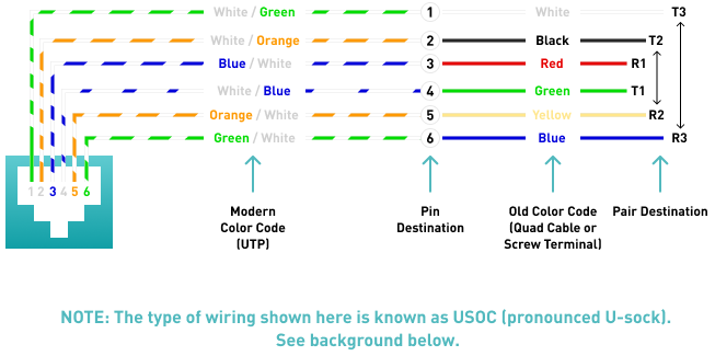
(USOC Wiring Diagram) Telephone wiring for a phone outlet is typically either 1, 2 or 3 pairs (2, 4, or 6 conductor). Most cable nowadays is UTP (unshielded twisted pair). There may be instances where you may need to connect to or transpose from the old "quad" cable. The diagram below provides the transposition between these standards.
Pair 1 (T1 & R1)
Usually the primary dial tone or talk circuit is wired to the center two pins (pins 3 & 4) and is the white/blue and blue/white pair (AKA: T1 & R1 - tip 1 and ring 1). A standard single line phone draws dial tone from these center pins.
Pair 2 (T2 & R2)
The secondary circuit is wired to the two pins (pins 2 & 5) directly to the side of the center pins and is the white/orange and orange/white pair (AKA: T2 & R2 - tip 2 and ring 2). Depending on the application, the secondary circuit can either be the 2nd dial tone line on a two line phone, or the data/control circuit for an electronic key phone.
Pair 3 (T3 & R3)
The third circuit is wired to the two pins (pins 1 & 6) on the outside and is the white/green and green/white pair (AKA: T3 & R3 - tip 3 and ring 3). Depending on the application, the third circuit can either be the 3rd dial tone line on a three line phone or an accessory circuit for an electronic key phone.
BACKGROUND
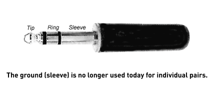
Tip & Ring
In telephony the terms that represent the conductors that comprise a circuit are known as "tip and ring". These terms stem from the early days of telephony when operators made telephone connections using 1/4" phono plugs similar to those used today for stereo headphones. The old systems also carried a third wire which was a ground. The "Tip" was the tip of the plug and was the positive (+) side of the circuit. The "Ring" was a conductive ring right behind the tip of the plug and was the negative (-) side of the circuit. Right behind the ring was the "Sleeve" which was the ground connection.
USOC (Universal Service Ordering Codes)
In the old days of telephony, USOC (pronounced U-sock) standards were used to simplify and standardize the various different wiring schemes for modular jacks.
RJ (RJ-11, RJ-45 Etc.)
The USOC standards consisted of many different Registered Jack Configurations which were abbreviated as "RJ" and had designations like RJ-11, RJ-12, etc. Today we still refer to modular jacks in the RJ designations but rarely use them to refer to a wiring standard that they were originally intended for. Even though it is technically incorrect, popular terminology today for the terms RJ-11, 12 or 14 refer to a 6 pin jack and RJ-45 refers to an 8 pin jack
The information on this page is an original copyrighted article. We welcome you to link this page from your website. However, copying this article in whole or in part is strictly prohibited.
Disclaimer:
Disclaimer: We have provided this article as general installation advice to our customers. We make no claims about the completeness or the accuracy of the information as it may apply to an infinite amount of field conditions. It is the responsibility of the person or persons using this information to check with all concerned parties, owners and local authorities, etc. before doing an installation. Users of this information agree to hold Atcom Inc. harmless form liabilities of any kind relating to the use of this information.
Also, be sure to check out our fiber solutions. For our customers, we sell pre-terminated fiber optic cables so they are able to connect them in their installation more easily.
