

Demand for fiber optic networks is growing to support increased network speeds and high- volume data transfers. Fiber optic patch cables support these demands by providing reliable high- speed connections. The fiber optic patch cable consists of cabling and connectors that connect to optical equipment supporting high-speed networks. Fiber optic patch cables are found almost everywhere; cable television networks (CATV), data centers, computer networks, and telephone networks. Fiber optic patch cables are put together by selecting and assembling the fiber types, cable styles, standard or special type fiber patch cord, connector style and types, polishing type, and jacket type.
Cable Types
Single-mode Fiber Optic Cable

Singlemode fiber optic patch cables support high-speed networks up to 50 times farther than multimode fiber optic cables. In addition, the narrower 9-micron core provides faster transmission speeds and long-distance communication ranges.

Multimode Fiber Optic Cable
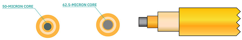
Multimode fiber optic cable supports short-range high-capacity networks where dependability is crucial. Multimode fiber equipment is also inexpensive, and as a result, it often forms the backbone of a building network, and horizontal cabling runs between buildings. In addition, the 50-micron or 62.5-micron cores provide the necessary bandwidth capabilities for high-volume data solutions.
Multimode versions
Multimode fiber comes in five versions – OM1, OM2, OM3, OM4, and OM5 – and provides 10 Gbit/s speed over short distances required by LAN enterprise and data center applications. In addition, the larger cores use multiple light modes enabling more data to pass through at a given time. The main difference between the five versions is the diameter, jacket color, optical source, and bandwidth.
| Cable Type | Core Size | Jacket Color | Optical Source | Bandwidth |
|---|---|---|---|---|
| OM1 | 62.5 | Orange | LED | 200MHz*km |
| OM2 | 50 | Orange | LED | 500MHz*km |
| OM3 | 50 | Aqua | VSCEL | 2000MHz*km |
| OM4 | 50 | Orange | VSCEL | 4700MHz*km |
| OM5 | 50 | lime Green | VSCEL | 28000MHz*km |
| MMF Category | Fast Ethernet | 1GbE | 10GbE | 40GbE | 100GbE |
|---|---|---|---|---|---|
| OM1 | 2000m | 275m | 33m | / | / |
| OM2 | 550M | 275M | 82M | / | / |
| OM3 | 2000m | / | 300m | 100m | 70m |
| OM4 | 2000m | / | 550m | 150m | 150m |
| OM5 | / | / | 550m | 150m | 150m |
> Duplex vs. Simplex Patch Cables
To remove a Duplex cable, follow these steps.
Simplex patch cable
A simplex fiber optic cable has a single strand of glass or plastic fiber as its core and one single connector on each end. Simplex fiber provides only one-way data transfer, so it works well for a network that moves data in a single direction. In addition, Simplex fiber optic cabling is excellent for long-distance communication because it carries a single light ray at a time.
Duplex patch cable
A duplex fiber cable consists of two glass or plastic fiber strands with a double connector on each end. Duplex fiber cables provide two-way communication where separate transmit and receive lines require simultaneous bi-directional data transfer.
You can turn a Duplex into a Simplex by just removing one part, the duplex clip.
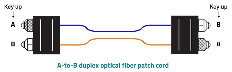
Duplex - Polarity A-B (flipped / straight through)
Polarity in fiber optics is directional concerning the direction light flows from one end of a cable to the other. To maintain polarity, the transmit (Tx) at one end of a cable connects to the receive (Rx) port at the other end. Cables, called A-B cables, support this connection style because they join the optical transmit (Tx) at one end to the optical receive (Rx) at the other end to sustain data transfer in a network.
Special Types of Fiber Patch Cords
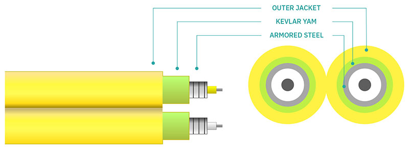
Armored Fiber Jumpers
Armored fiber cables have built-in metal shielding under the jacket, providing better optical fiber protection than traditional cables. The armored fiber cable also has the same flexibility as conventional cables. In addition, armored cables protect from environmental hazards such as solvents, moisture, dust, and damage-causing animals.
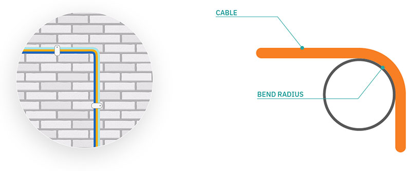
Bend Insensitive Fiber Patch Cord (What is it, what are the benefits)
Patch cables have a limit on how much bend is allowed before the fiber inside breaks. The amount a patch cable can bend before being damaged is called the bend radius. Bend insensitive patch cables can bend beyond conventional cable specifications without causing the fiber stress damage that allows light to leak out. Bend insensitive cables are typically applied to applications including distribution racks and in buildings where the cable is required to bend around wall corners and other fixtures.
Mode Conditioning Fiber Patch Cord
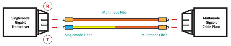
Mode conditioning patch cables increase your bandwidth without having to run a whole new fiber-optic network. Gigabit Ethernet transceiver modules operate for both single-mode and multimode applications. However, a network that uses multimode cables may experience extra signal generation in the cable that confuses the receiver at the receiving end and reduces cable operating distances.
A mode conditioning patch cord eliminates multiple signals by providing a single-mode launch that is offset from the center of the multimode fiber. The offset point creates a launch that is similar to typical multimode LED launches. At the start and end of the mode-conditioning patch cord is a small section of single-mode fiber, coupled at an offset to a multimode cable in the center. The offset creates an LED launch that is typical of standard multimode cords, eliminating the extra signals.
Connector Styles
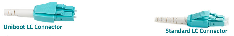
Uniboot Connectors (What they are, what are the benefits)
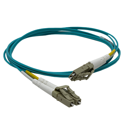
LC uniboot connectors integrate two fibers into a single cable. This design reduces the number of cables in a high-density cabling installation by reducing cable count by half and eases cable management. This design is different from the standard duplex fiber-optic connector that has a single fiber in two separate cables.
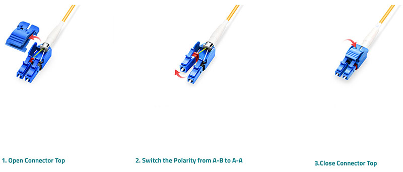
Switchable Uniboot connectors
Switchable uniboot connectors can be opened, without tools, to allow a technician to change the polarity from A-B to A-A or A-A to A-B.
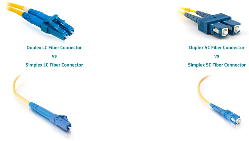
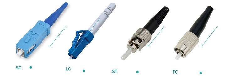
Connector Type: LC, SC, ST, or Others
A connector is located at each end of the fiber patch cable to provide a cabling attachment to the transmit and the receiving device. There are many types of connectors. The most common types of cable connectors are Lucent Connectors (LC), Subscriber Connectors (SC), and Straight Tip (ST). Connectors are designed for a specific application or to improve connection quality and installation density. Ease of connection, low cost of manufacture and operation, interchangeability, durability, and low coupling loss determine connector quality.
Standard fiber patch cords have the same connector type on both ends, such as LC to LC fiber patch cord and SC to SC fiber patch cord. Hybrid fiber patch cords have different connectors on each end, like LC to SC. If the port type of devices on both sides are the same, you can choose the same-connector type fiber patch cord. If the port type is not the same on both devices, choose a hybrid cable.
Polishing Type: PC, UPC, and APC
Do you know the difference between UPC and APC?
Fiber optic connectors are designed and polished into three shapes to minimize back reflection. The three fiber optic connector polish types are Physical Contact (PC), Ultra Physical Contact (UPC), and Angled Physical Contact (APC). PC connectors are black, APC connectors are green, and UPC connectors are blue to simplify identification. Always use the same polish types together, or the connection will have high insertion loss.
APC is better suited for high bandwidth applications and long-distance links, such as FTTx, passive optical network (PON), and wavelength division multiplex (WDM). On the other hand, UPC is better suited for optical systems that are less sensitive to insertion loss, such as digital TV and telephony.
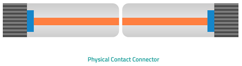
Physical Contact Polish
The Physical Contact (PC) polish type has a cylindrical cone head with a return loss of about - 40dB. OM1 and OM2 multimode fiber use the PC polish type.
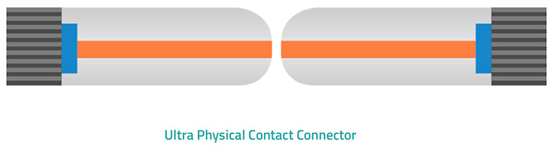
Ultra Physical Contact Fiber Connector
The Ultra Physical Contact (UPC) polish type has a similar, slightly more conical head shape and undergoes extended polishing. As a result, the surface and performance improve return loss to -50dB or higher. However, the head degrades over time with repeated connections and disconnections due to the precision contact surface.
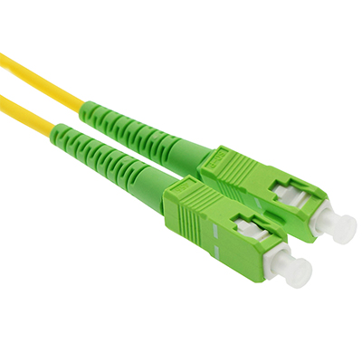
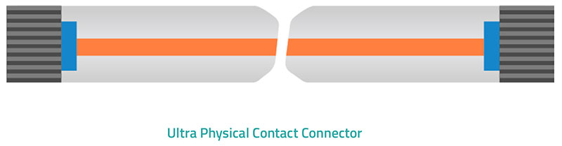
Angled Physical Contact Fiber Connector
The Angled Physical Contact (APC) polish type has a slightly angled tip with an end face radius at an 8° angle. This design minimized the back reflection too -60dB.
Jacket Type: PVS or LSZH
Two jacket types, Polyvinyl Chloride (PVC) and Low Smoke Zero Halogen (LSZH) combine and protect cable parts and identify the cable types. PVC provides a flexible jacket type for indoor applications used at average temperatures. LSZH provides a less flexible flame retardant jacket that offers better protection from extreme temperatures and high traffic.
Custom vs. Stock
Custom patch cables are made-to-order in the USA by highly trained technicians can be constructed of premium components. Choose any length from 6 inches up to 30 meters, any of 11 colors, and any connector type to fit your custom installation needs. Connector options include LC, SC, and ST. We will keep you informed of your order status from start to finish so you can plan your installation accordingly. You will receive an order confirmation immediately, a ship date within 24 hours, and tracking information once your custom cables ship out. Our custom fiber optic patch cables are perfect for patching out from your fiber optic enclosures to your SPF transceivers, network switches, or media converters.
Stock patch cables can be ordered only in modular sizes and options. The stock patch cable will be available in bulk and selected for performance and durability. Some other downsides are that the cable is not guaranteed to fit your application physically and isn’t guaranteed to operate within the tolerances of that application. It may be necessary to order cables that are too long and add unnecessary bulk and cable bends to the run. Stock cables may be inexpensive, but they may fail more often and at critical moments. If an installation is on a tight timeline, it might be better to order custom cables to ensure operation and compatibility.
Conclusion
In this guide learned about selecting and assembling the parts of fiber optic patch cables, how they can be assembled and used for cost and installation efficiency. Hopefully, this guide has provided information showing that fiber patch cord allows individualized construction to improve networks to achieve larger bandwidths and greater speeds. Contact a professional for additional information that will satisfy your individual requirements.