SALES & ORDERS
Custom Cable Manufacturing in the USA Since 1997
Home of 
Free Ground shipping on orders over $250

Use code SHIP4FREE Exclusions Apply
Important!
Eligible Products Only | Free Shipping Exclusions May Apply to Heavy, Electronics & Bulky ItemsTake advantage of our custom-built Configurator pages to speed up your shopping experience. Each page makes it simple to narrow down to exactly the product you need with just a few choices from you. Whether you need patch cords, fiber assemblies or MTP trunk cables we've got an Easy Configurator Tool that's right for you!

QuickTrex MTP Assembly Builder Tool
1/4
Jacket Types
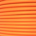
Indoor
This is a plenum rated distribution type fiber with a durable jacket which provides added protection during installation. It is suitable for all indoor applications where fiber optic cabling is needed. It utilizes 900µm Tight Buffers, Aramid yarn strength members, and exclusive use of Corning® optical fibers. This cable is rated for all indoor installations, including plenum rated spaces. A cable rated for plenum installation will have low-smoke characteristics as defined by the NFPA (National Fire Protection Agency).
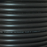
Indoor/Outdoor
Indoor/Outdoor cables are approved for use in underground conduits, even if the possibility of water infiltration exists due to its water blocking aramid strength members. Fiber construction is with 900µm Tight Buffers, and exclusive use of Corning® optical fibers. It can also be used for standard Outdoor applications since it is UV resistant, but it is not rated for direct burial (see Outdoor Fiber). The advantage of using Indoor/Outdoor over standard Outdoor cable is that it does not have the 50 foot restriction for indoor installation that standard outdoor cable has. It has a durable jacket that adds extra protection during installation and in rugged applications.
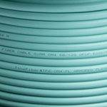
Indoor Ultra Thin Micro Armor
Micro Armor fiber utilizes a Stainless Steel Coiled Tubular Armor which has the smallest outer diameter of any armored fiber, making routing and installation faster and easier. These cables are up to 65% smaller, and 75% lighter than conventional Aluminum Interlocking Armor (AIA). It provides the strongest armor with maximum bend radius and is crush and rodent resistance for multiple usages. Kevlar Fiber Strands add tensile strength and flexibility, and this cable has exclusive use of Corning® optical fibers. This cable is rated for all indoor installations, including plenum rated spaces. A cable rated for plenum installation will have low-smoke characteristics as defined by the NFPA (National Fire Protection Agency).
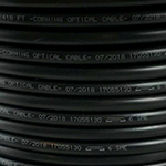
Outdoor Loose Tube
This Corning® Altos® Loose Tube fiber has a medium-density polyethylene jacket. This jacket is rugged and durable, while providing superior protection against UV radiation, fungus, abrasion and other environmental factors. It is an all-dielectric (non-armored) gel-free cable designed for outdoor and limited indoor use for campus backbones in lashed aerial and duct installations. The cable is fully waterblocked using craft-friendly, water-swellable materials, and the all-dielectric gel-free cable construction requires no bonding or grounding.
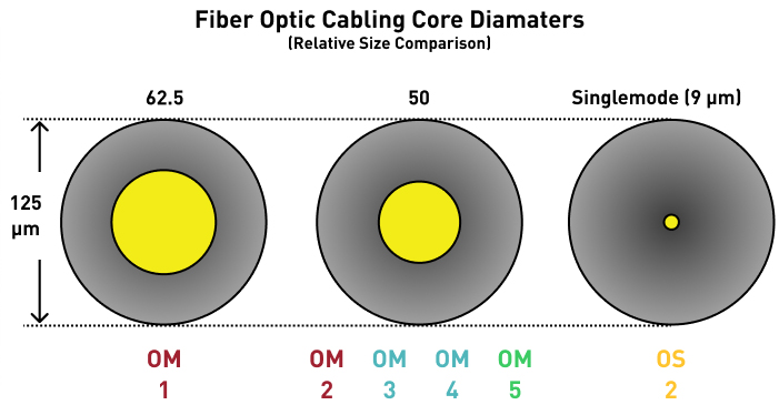
N/A = Not Supported/Not Applicable
| Designation | Core/Cladding Diameter (µm) | Type | Fast Ethernet 100BASEFX | 1Gigabit Ethernet 1000BASE-SX |
1 Gigabit Ethernet 1000BASE-LX | 10 Gigabit Ethernet 10GBASE-SR | 40 Gigabit Ethernet 40GBASE-SR4 | 100 Gigabit Ethernet 100GBASE-SR4 | 40G- SWDM4 | 100G- SWDM4 |
|---|---|---|---|---|---|---|---|---|---|---|
| OM1* | 62.5/125 | Multimode | 2km | 275 Meters | 550 Meters (mode conditioning cable may be required) | 33 Meters | N/A | N/A | N/A | N/A |
| OM2* | 50/125 | Multimode | 550 Meters | 82 Meters | ||||||
| OM3 (Laser Optimized) | 50/125 | Multimode | 550 Meters | 300 Meters | 100 Meters | 100 Meters | ||||
| OM4 (Laser Optimized) | 50/125 | Multimode | 400 Meters | 150 Meters | 150 Meters | 400 Meters | 100 Meters | |||
| OM5 (Wideband MMF) | 50/125 | Multimode | 100 Meters | 150 Meters | ||||||
| Singlemode (OS1/OS2) | 9/125 | Singlemode | 2km (FX) / 10km (LX10) | N/A | 10 km at 1310 nm | 10 km+ | N/A | N/A | N/A | N/A |
Working with MTP®/MPO cable assemblies can be confusing, especially regarding polarity. But, for high density applications MTP is the best choice due to reduced labor costs, less congestion in cable pathways and spaces, and overall optical performance and reliability. Let’s break down some common questions regarding MTP polarity methods.
Let’s break down some common questions regarding MTP polarity methods.
MTP/MPO Polarity
Optical fiber networks require two fibers to make a complete circuit. The matching of the transmit Tx signal to the receive Rx equipment is referred to as polarity, and a transmit and receive side on optical transceivers usually use a duplex fiber connector to maintain the polarity. On most cabling systems, maintaining polarity just requires that the A side of one connector pair matches the B side of the other connector pair, with fiber connectors such as ST, LC, SC, and MTRJ.
MTP/MPO high density network design requires its own set of rules regarding maintaining polarity throughout the link. These three polarity methods are commonly referred to as Method A, Method B, and Method C, and we will discuss the difference further here.
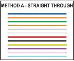
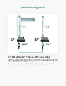
Method A – Straight Through
This type of MTP cable has a key up key down position, and the fiber remains the same straight through the cable. Therefore each fiber is in the same position on each end of the cable. Fiber 1 in the cassette mates to Fiber 1 in the cable assembly, which mates to Fiber 1 in the end cassette.
The transmit/receive flip must happen with the patch cords either at the beginning or end of the link to ensure proper transceiver polarity.
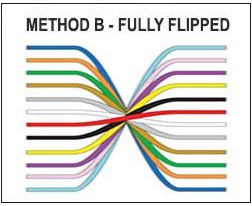
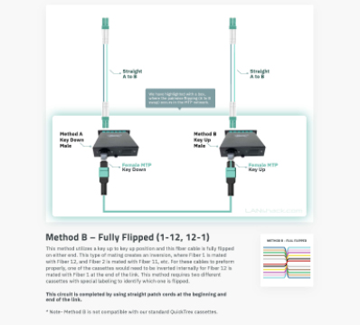
Method B – Fully Flipped (1-12, 12-1)
This method utilizes a key up to key up position and this fiber cable is fully flipped on either end. This type of mating creates an inversion, where Fiber 1 is mated with Fiber 12, and Fiber 2 is mated with Fiber 11, etc. For these cables to preform properly, one of the cassettes would need to be inverted internally for Fiber 12 is mated with Fiber 1 at the end of the link. This method requires two different cassettes with special labeling to identify which one is flipped. This circuit is completed with using straight patch cords at the beginning and end of the link.
*Note- method B is not compatible with our standard QuickTrex cassettes.
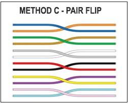
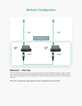
Method C – Pair Flip
Method C and Method A are very similar, with the main difference being the flipping of the patch cords in the link. This method uses key up key down, and the polarity flip takes place within the cable itself. Each adjacent pairs of fiber at one end are flipped at the other end. So Fiber 1 and Fiber 2 becomes Fiber 2 and Fiber 1 at the other end, and so on.
This circuit is completed by using straight patch cords at the beginning and end of the link.
MTP/MPO Connector Types
Although most people in the industry refer to this connector as MTP, it is actually correct to also call it MPO. The term MTP is a registered trademark of USConec and identifies their specific brand of the MPO-style connector. The name MPO stands for Multifiber Push On, and typically consists of a 12 strand Ribbon Fiber that is terminated to a single compact push on connector.
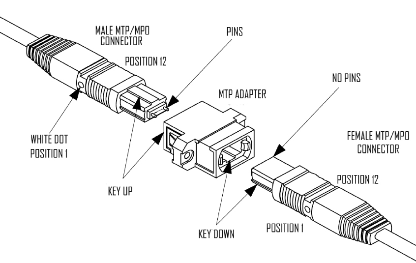
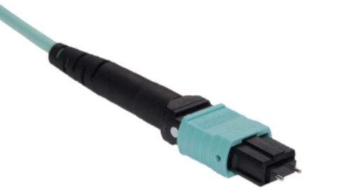 Male MTP/MTO Connector
The pins on the MTP/MPO connector signifies that is it a Male connector.
The white dot on the right, signifies position 1 on the MTP pinout.
The raised tab on the top of the connector signifies it is in the key up position.
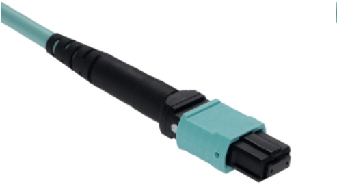 Female MTP/MTO Connector
The lack of pins on the MTP/MPO connector signifies that it is a Female connector.
The white dot on the right, signifies position 1 on the MTP pinout. The raised tab on the top of the connector signifies it is in the key up position.
MTP Strand Counts
There are three popular MTP strand counts available on the market today.
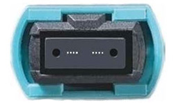 MTP 8
MTP 8The MTP 8 Connector utilizes 8 of the 12 fibers in a standard 12 Fiber Connector. QSFP applications use the outer four fiber spots (1 – 4 and 8-12) of the MTP connector with four fibers used to transmit and four to receive. Method B is the most commonly used polarity method for a MTP 8.
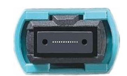 MTP 12
The MTP 12 Connector is the most popular choice for a MTP connector and is recognized as industry standard. Method A, B, and C are available in a MTP 12. Method A is the recommended polarity method.
MTP 24The MTP 24 is the most cost effective and high-density solution for MTP, as this connector is able to harness 24 fiber strands in one connector. There are various polarity options for MTP 24, but Method A is recommended, and is standard on our QuickTreX assemblies.
Connecting MTP Connectors
When connecting, or mating, two MTP connectors together, you will need an MTP adapter to accomplish this. The male connector should be in the key up position, and the female in the key down position.
MTP Cassettes
Maintaining proper polarity across your network is also applicable when choosing a cassette. Cassettes come in a few different forms: 12 Fiber (1 x 12), 24 Fiber (2 x 12), and 24 Fiber (1 x 24). It is especially important to make sure the MTP configuration on your MTP Trunk Assembly or MTP Fanout Assembly is compatible with the MTP Cassette you choose.
Cassettes will be labeled as Method A/C or Method B. The main difference here is orientation of the way the MTP cables are mated together. Alignment pins are pre-installed in the MTP/MPO connector located inside the cassette. These pins precisely align the mating fibers in the MTP/MPO connectors at either end of the cables that plug into the cassettes.
For Method A or Method C Polarity:
Method-A cassettes make a key up to key down connection between the internal MTP connector and the MTP cable connector.
The cassettes will already be in a key up position, and when plugging in your MTP connector it needs to be in the key down position.
For Method B Polarity:
Method-B cassettes make a key up to key up, key down to key down connection. For these cables to perform properly, one of the cassettes would need to be inverted internally for Fiber 12 is mated with Fiber 1 at the end of the link. This method requires two different cassettes with special labeling to identify which one is flipped.
One cassette will be in the key up position, with the MTP cable also being key up.
One cassette will be in the key down position, with the MTP cable also being key down.
Method B cassettes are not recommended for Singlemode APC fiber applications, because the angles of the mating connectors do not line up properly with this configuration and are not sufficient for low loss applications.
*QuickTreX cassettes support a method A/C configuration, and are not compatible with Method B.
Method B in Parallel Optics
Method B polarity is particularly useful in regard to 40G parallel optic applications, and direct switch to switch connectivity. Method B MTP cables are also referred to as a QSFP/QSFP+ cable or direct attach 40GBASE-SR4, 40GBASE-PLR4 or 40GBASE-PLRL4. This orientation is useful because instead of an alternating Tx to Rx duplex pattern, 40G parallel optics utilizes the flipped Pin 1 to Pin 12, Pin 12 to Pin 1 pinout.
Female to Female type B trunk cables can also be used for a direct switch to switch connectivity going directly into 40G transceivers, or with an MTP adapter, used to connect a patch panel to a QSFP+ transceiver.
Method B in Parallel Optics
We have talked about the different types of MTP polarities, and how to properly mate two MTP connectors. The last step in a standard MTP application is breaking out the high-density fiber strands into standard fiber connectors.
If you are using a cassette, then you will need standard fiber jumper cables to complete the polarity methodology. If you are using an adapter, then you will be connecting the MTP trunk cable to an MTP Fanout Assembly which will have standard fiber connector fanouts. The MTP Fanout Builder will go into more depth on configuration there, so let’s focus on a MTP cassette method with patch cables.
There are two types of duplex fiber patch cables as defined in the TIA standard: A to A, and A to B. Maintaining proper polarity requires the B Tx signal to connect to the A Rx signal.
A to B patch cables are also known as “straight-through”
A to A patch cables are also known as “flipped”
Patch cords made with individual single fiber connectors at each end allow the flexibility for connections to be “swapped” when a polarity reversal is required. Our QuickTreX Custom USA fiber optic patch cables will provide the ability to be swapped.
The below diagrams are a macro overview of the entire MTP trunk cable to cassette connectivity flow. We have highlighted with a box, where the pairwise flipping (A to B swap) occurs in the MTP network.
Our Offerings
At LANshack we have been manufacturing custom fiber optic cabling with premium Corning Glass in the USA for over 20 years. Our QuickTreX custom line of MTP Trunk Cables, MTP Fanout Cables, MTP cassettes and enclosures are a complete robust solution for all your MTP needs
MTP Accessories
There are a variety of hardware accessories that go along with most MTP/MTO installations. It's important to match what you need with what you have for maximum performance and full compatibility.
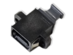 MTP Coupler
An MTP coupler is used to connect two 12 fiber MTP male to MTP female connectors together.
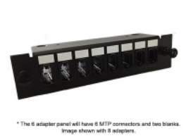 MTP Adapter Panel
 This can also be accomplished using an MTP adapter panel which will have 6 or 8 MTP/MTO couplers within the panel. This is useful to connect an MTP assembly with an MTP Fanout cable - Male to Female Connections
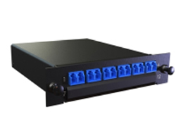 MTP Cassette
 A cassette will have an MTP connector in the back which will be a male connector. Therefore, MTP cables that plug into the cassettes will be a female cable.
MTP Cabling and Fanouts
Matching your MTP trunk assembly to the appropriate fanout cabling situation isn't always simple. Here are some of the choices for what you might need to match with what you have for maximum performance and full compatibility.
 12 12 A 12 Fiber Cable will have one 12 Fiber MTP Connector on each end
 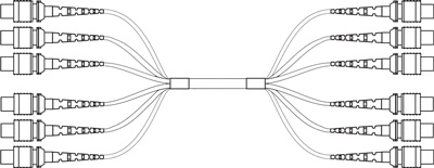 72 12x6 This 72 Fiber MTP Trunk Assembly will have (6) 12 Fiber MTP Connectors on each end
 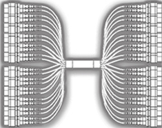 288 24x12 This 72 Fiber MTP Trunk Assembly will have (6) 12 Fiber MTP Connectors on each end
 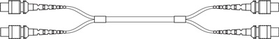 24 12x2 This 24 Fiber MTP Trunk Assembly will have (2) 12 Fiber MTP Connectors on each end
 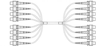 96 12x8 This 96 Fiber MTP Trunk Assembly will have (8) 12 Fiber MTP Connectors on each end
 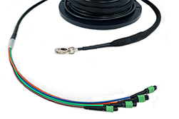 Breakouts Customized breakouts available from 12 inches to 48 inches
 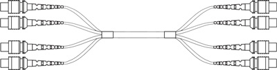 48 12x4 This 48 Fiber MTP Trunk Assembly will have (4) 12 Fiber MTP Connectors on each end
 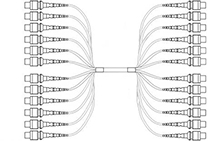 144 12x12 This 144 Fiber MTP Trunk Assembly will have (12) 12 Fiber MTP Connectors on each end
 Pulling Eyes
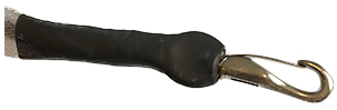
A pulling eye is designed to be attached to a pull string that runs the full length of your conduit. Your assembly is then pulled through the conduit via the pull string. It can also be used to pull your assembly through duct work, in wall cavities, or other areas where routing needs to take place. Our pulling eyes include a heavy-duty swivel hook to prevent the cable from twisting during the pull. The metal pull hook is attached to a designated pull string inside of your assembly usually consisting of Kevlar so that you are not pulling on the fiber strands themselves. The pulling eye includes heat shrink tubing that covers the back side of the pull hook, and the pull basket that contains your fiber optic connectors.
The pull basket is constructed with super strong polyethylene mesh that tightens itself around the strands and connectors keeping them securely in place during install. The connectors are also staggered inside of the pull basket for less bulk, and each connector is individually plastic wrapped to prevent contamination by pulling lubricants and other debris. Our pulling eyes are always recommended as they make your pull much easier while providing further protection of your connectors.
 TECH TIP
We always recommend pulling eyes on both ends, even if you’re only pulling one end of the assembly. This helps protect the back side of your assembly’s connectors and prevent damage. The pull hook can be secured on the back end to prevent twisting and flapping of your connectors during install.
