Fiber Specifications
The usual fiber specifications you will see are size, attenuation and bandwidth. While manufacturers have other specs that concern them, like numerical aperture (the acceptance angle of light into the fiber), ovality (how round the fiber is), concentricity of the core and cladding, etc., these specs do not affect you.
Fiber Itself
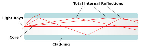
Fiber Optics, as we said, is sending signals down hair-thin strands of glass or plastic fiber. The light is "guided" down the center of the fiber called the "core". The core is surrounded by a optical material called the "cladding" that traps the light in the core using an optical technique called "total internal reflection." The core and cladding are usually made of ultra-pure glass, although some fibers are all plastic or a glass core and plastic cladding. The fiber is coated with a protective plastic covering called the "primary buffer coating" that protects it from moisture and other damage. More protection is provided by the "cable" which has the fibers and strength members inside an outer covering called a "jacket".
Multimode & Singlemode Fibers
Multimode & Singlemode fiber are the two types of fiber in common use. Both fibers are 125 microns in outside diameter - a micron is one one-millionth of a meter and 125 microns is 0.005 inches- a bit larger than the typical human hair. Multimode fiber has light traveling in the core in many rays, called modes. It has a bigger core (almost always 62.5 microns, but sometimes 50 microns ) and is used with LED sources at wavelengths of 850 and 1300 nm (see below!) for slower local area networks (LANs) and lasers at 850 and 1310 nm for networks running at gigabits per second or more. Singlemode fiber has a much smaller core, only about 9 microns, so that the light travels in only one ray. It is used for telephony and CATV with laser sources at 1300 and 1550 nm. Plastic Optical Fiber (POF) is large core ( about 1mm) fiber that can only be used for short, low speed networks.
Step index multimode
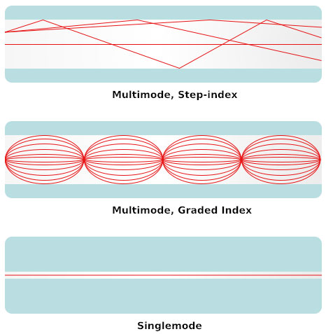
was the first fiber design but is too slow for most uses, due to the dispersion caused by the different path lengths of the various modes. Step index fiber is rare - only POF uses a step index design today.
Graded index multimode
fiber uses variations in the composition of the glass in the core to compensate for the different path lengths of the modes. It offers hundreds of times more bandwidth than step index fiber - up to about 2 gigahertz.
Singlemode
fiber shrinks the core down so small that the light can only travel in one ray. This increases the bandwidth to almost infinity - but it's practically limited to about 100,000 gigahertz - that's still a lot!
Size Matters
Fiber, as we said, comes in two types, singlemode and multimode. Except for fibers used in specialty applications, singlemode fiber can be considered as one size and type. If you deal with long haul telecom or submarine cables, you may have to work with specialty singlemode fibers.
Multimode fibers originally came in several sizes, optimized for various networks and sources, but the data industry standardized on 62.5 core fiber in the mid-80s (62.5/125 fiber has a 62.5 micron core and a 125 micron cladding.) Recently, as gigabit and 10 gigabit networks have become widely used, an old fiber has been revived. The 50/125 fiber was used from the late 70s with lasers for telecom applications before singlemode fiber became available. It offers higher bandwidth with the laser sources used in the gigabit LANs and can go longer distances. While it still represents a smaller volume than 62.5/125, it is growing.
Fiber Types and Typical Specifications
| Core/Cladding | Attenuation | Bandwith | Applications/Notes |
|---|---|---|---|
| Multimode Graded-Index | |||
| @850/1300 nm | @850/1300 nm | ||
| 50/125 microns | 3/1 dB/km | 500/500 MHz-km | Laser-rated for GbE LANs |
| 50/125 microns | 3/1 dB/km | 2000/500 MHz-km | Optimized for 850 nm VCSELs |
| 62.5/125 microns | 3/1 dB/km | 160/500 MHz-km | Most common LAN fiber |
| 100/140 microns | 3/1 dB/km | 150/300 MHz-km | Obsolete |
| Singlemode | |||
| @1310/1550 nm | |||
| 8-9/125 microns | 0.4/0.25 dB/km | HIGH! ~100 Terahertz | Telco/CATV/long high speed LANs |
| Multimode Step-Index | |||
| @850 nm | 500/500 MHz-km | ||
| 200/240 microns | 4-6 dB/km | 500/500 MHz-km | Slow LANs & links |
| POF (plastic optical fiber) | |||
| @ 650 nm | @ 650 nm | ||
| 1 mm | ~ 1 dB/m | ~5 MHz-km | Slow LANs & links |
Even connections between 62.5/125 and 50/125 can cause loss of 3 dB or more - over half the power.
Featured Fiber Optic Products

Read on for more fiber optic tutorial information..


We welcome you to link this page from your website; however, copying this article in whole or in part is strictly prohibited.
Disclaimer: We have provided this article as general installation advice to our customers. We make no claims about the completeness or the accuracy of the information as it may apply to an infinite amount of field conditions. It is the responsibility of the person or persons using this information to check with all concerned parties, owners and local authorities, etc. before doing an installation. Users of this information agree to hold Atcom Inc. harmless form liabilities of any kind relating to the use of this information.