


 Installing Cat 6E (and Cat 5E) Shielded Modular Plugs using the QuickTreX™ System
It is now not only possible but also easy to field terminate category 6E (and Category 5E) Shielded modular plugs thanks to the new QuickTreX™ Category 6E Shielded modular plug which contains a new Heavy Duty Shield and the Patented Conductive NEXT Reduction System. The shielding material is heavy duty to assure solid connections to both the drain wire and also to the shielding connection of the receptacle body. The quality of the shielding virtually eliminates any chance for ANEXT entering the cable. The Internal Conductive Loading Bar is molded from a material that substantially reduces the affect of NEXT within the Plug Body. The conductors are isolated by plastic that absorbs the NEXT from between the conductors and channels it away so that the Plug can perform to Category 6E levels and above. When assembled onto Category 6E patch cable it will pass all TIA/EIA requirements for NEXT and Return Loss, etc.. If done correctly, your patch cable will pass Cat 6E Component level testing! This will help your Category 6 channel maintain increased headroom to assure your network operates at its best.
 PLEASE NOTE:
In the process of designing a Shielded plug for Category 5E cabling, it was realized that a heavy duty shield was needed there also (as for Cat 6E) to assure a good shielding connection. Our engineers decided to use the same shielding metal material for the Cat 5E plugs (as the Cat 6E). Since the Shielding material is the most costly of all of the components, it was decided that it would be much more efficient and cost effective to offer the same Cat 6E Shielded plug to be used on Category 5E systems as well as Cat 6E. This will in effect add more headroom and robust performance to Cat 5E Cabling at no additional cost.
1 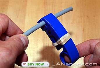
Slip on the strain relief boots over the cable and proceed to skin off the Cable's jacket about 2 inches from the end. In this illustration we are using our EZ-Cable Stripper tool. Due to the fact that many Cat 6 shielded cables have very thick jackets, it may be necessary to put a rubber band around the tool thereby reducing the pressure on the cutting blades and making a shallower cut. |
2 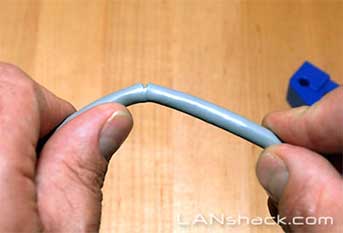
Gently bend the cable back and forth at the strip point to finish the process of skinning. Remove the cable's jacket |
3 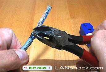
Cut off the entire foil wrap leaving the silver color drain wire and the four pairs. Pictured above is the Klein - 6" Diag.-Cutting Pliers - Model# D252-6. |
4 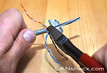
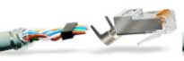
Fan out the four pairs and cut off the center spine. Then bend the Orange and Brown Pairs (assuming you are wiring for 568-B scheme) to the outside leaving the Blue and Green pairs in the center. |
5 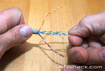
At this point we will prepare the two center pairs (Blue and Green pairs) first. Remove the twists in the Blue and Green pairs leaving at least 2 twists at the end. The twisted portion that remains should be roughly 1/4" from the skinned end. It may be necessary to remove and then redo the twists either tighter or looser so that they fall out properly. |
6 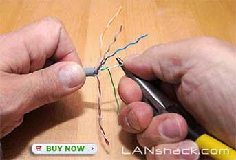
At this point we will prepare the two center pairs (Blue and Green pairs) first. Remove the twists in the Blue and Green pairs leaving at least 2 twists at the end. The twisted portion that remains should be roughly 1/4" from the skinned end. It may be necessary to remove and then redo the twists either tighter or looser so that they fall out properly. |
7 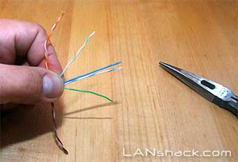
Arrange the straightened pairs as shown with the blue pair in the center and the green pair to the sides of it. Then move the green pair inward making two straightened pairs. |
8 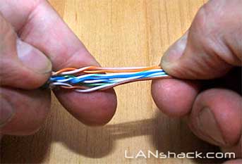
Repeat the process that we did in step # 5 but only with the remaining Orange and Brown pairs and arrange them as shown in the illustration. Notice that there is between 1 or 2 twists left in the pairs where they leave the jacket. |
9 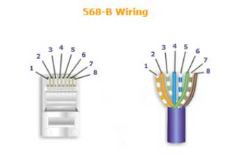
Check your wire sequence to see that it matches the sequence below. Then proceed to make the straight portion of the wires are perfectly straight and perfectly pressed together in a very compact way. |
10 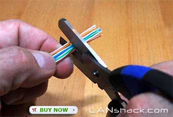
Use a pair of high quality electrician's wire scissors with serrated blades to make a straight cut across the bundle at about an inch back from the end. The strongly recommend the QuickTreX™ Wire Surgeon™ Wire and Kevlar Scissors for this purpose to get a perfectly clean and straight cut. |
11 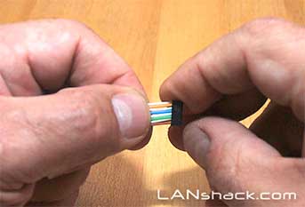
While holding the cut bundle together between the thumb and index finger, proceed to slide the black loadbar on to the wires with the hollow portion of the loadbar facing the wire bundle. A slight amount of wiggling may be required but get all of the wires into the holes of the loadbar. Then slide the loadbar all the way back to the twists and use some pulling pressure to get the loadbar as far back as possible which should leave about 1/4" of twisted wires showing. NOTE: It is not necessary to cut the wires on an angle for this step as we had recommended in previous tutorials. |
12 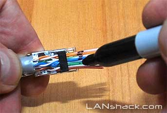
Put the wire assembly over a connector so that the jacket is about 1/8" into the connector. Then mark the wire at the point where it is even with the end of the connector. Use the electrician's wire scissors to cut the wires straight across at the point where you made the mark. |
13 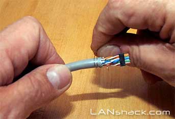
Take the silver color bare drain wire which should be about two inches long and wrap it around the cable's jacket as shown in the illustration. Please look at the assembly shown in the illustration. Your assembly should look like this. |
14 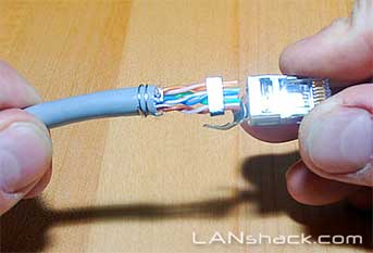
With the Orange pair furthest away from you and the Brown pair closest, slide the connector on to the assembly with the pins facing up and the locking clip facing down. Push the assembly into the connector with a slight wiggling motion to make the ends of the wires go all the way to the end of the connector. It may be necessary to use moderately firm pushing to make this happen. At this point it is advisable to use a magnifying glass or jeweler's loop to look directly into the face of the connector to see that the wires have gone all the way in. |
15 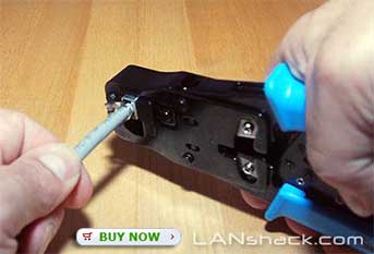
Use a high quality Industry Standard Crimper such as our QuickTreX™ Ratchet Type Crimper for RJ-45 to crimp the eight pins down making the connection to the eight wires. Push the connector all the way into the crimper and use a firm squeezing motion to assure a full crimp. |
16 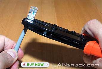
Next, crimp the shield clamp down to the drain wire and the cable's jacket. You may start this process by using the long nose pliers to bend the two silver arms inward and around. For best results we recommend finishing the crimp with a 0.256" Hex crimper such as our QuickTreX™ Hex Crimper for Shielded Assemblies as shown in the illustration. |
17 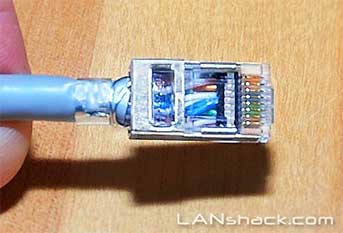
Here is what the connector should look like when finished. Notice that the twists in the wires are visible looking down into the connector body. |
18 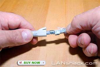
(Optional) Slide the boot over the connector. |
3
 |
Complete the process over on the other end of the cable. Then use a cable tester that tests the four pairs plus the shield such as our LANTEST-PRO Cable Tester. | |
Featured Products
 QuickTreX® Category 6E (& 5E), Shielded Modular Plugs w/ Loadbar - Bag of 50
 Heavy duty Shielding assures solid connections to both the drain wire and also to the shielding connection of the receptacle body. The quality of the shielding virtually eliminates any chance for ANEXT entering the cable.
- Included Loadbars for ease of installation and virtually foolproof results.
- Staggered "One Up, One Down" design for enhanced performance and reduction of crosstalk.
- High quality 50 micron gold connecting surfaces.
- Dual Use – for both Solid and Stranded conductor wire.
- Can terminate 28AWG to 22AWG.
- Individual wire thickness with insulation should fall between .037" and .042


Usually ships within 24 hours.
QT-LS6S-P50

Crafted in Germany of durable ice-tempered Solingen stainless steel that holds up under extreme use.
This wire shear is precision designed for clean cutting and specially ground for use with wire, braiding, etc. Slight serrations on the blade prevent wire slippage and make dependable precise cuts possible.
The ergonomically designed soft rubber handle provides fatigueless use suitable for right or left-handed people. Whether you are a professional or amateur, you will agree that these are the best wire cutting scissors that you have ever used!
Usually ships within 24 hours.
QT-LS6S-P50
We welcome you to link this page from your website. However, copying this article in whole or in part is strictly prohibited.
Disclaimer: We have provided this article as general installation advice to our customers. We make no claims about the completeness or the accuracy of the information as it may apply to an infinite amount of field conditions. It is the responsibility of the person or persons using this information to check with all concerned parties, owners and local authorities, etc. before doing an installation. Users of this information agree to hold Atcom Inc. harmless form liabilities of any kind relating to the use of this information..
Shielded vs Unshielded
A shielded patch cable will have a metallic housing on the modular plug. Unshielded will have a clear, plastic body. Shielded also offers protection from alien crosstalk, or EMI.
What is a strain relief boot?
A strain relief boot protects your cable from bends