Before we start to discuss the differences between the EIA/TIA-569 (Commercial Building Standard for Telecommunications Pathways and Spaces) and the National Electrical Code (herein referred to as “NEC” or “the code”), as they pertain to conduit installations, let’s keep in mind, the fact that the NEC is the law of the land, and the EIA/TIA-569 is a recommended standard.
What is TIA 569?
TIA-569 is a Telecommunications Industry Association (TIA) standard that provides guidelines for pathways and spaces used in commercial building telecommunications infrastructure. It outlines the design and implementation of cable pathways, telecommunications rooms, equipment rooms, and entrance facilities to ensure efficient and scalable network installations.
The standard helps architects, engineers, and IT professionals design buildings with structured cabling systems that support various telecommunications services, including voice, data, and video. By following TIA-569, organizations can maintain consistent, organized, and future-proofed cabling infrastructures.

One of the key aspects of TIA-569 is its emphasis on proper cable management and space allocation.
The standard defines requirements for conduits, cable trays, access floors, and ceiling pathways to ensure that cables are protected from physical damage and electromagnetic interference. It also provides guidelines for ventilation, accessibility, and separation of different types of cabling to prevent performance degradation.
Compliance with TIA-569 enhances network reliability, reduces maintenance costs, and supports future technology upgrades by ensuring that telecommunications spaces are designed with scalability and flexibility in mind.
Important Note: Always refer to local codes, in addition to the NEC, or 569, when planning, or performing an installation.
If you ever read through the NEC, you will notice that along with almost every rule, there will be a list of exceptions to the rule. The exceptions recognize the fact that these installations are done in the real world. There are many instances where a rule may not apply, or not be practical, or may make certain installations impossible to do. The writers of the code, on a regular basis, receive feedback from, and consult with, many building industry sources, and make changes accordingly. The NEC is revised every three to four years.
Featured Products


It seems that the 569 standard is much more stringent on many aspects of conduit installations, than the NEC. There can be many circumstances where a telecommunications professional, with good intentions, may have no other choice but not to comply with the 569 standard. I do not believe that any law, set of rules, guidelines, etc., that are made so strict that people choose (or have no other choice) not to follow them, will properly serve the group of people (or industry) that they were designed for. Luckily, the TIA/EIA-569 standard is a living document, which means that it can be revised or changed, due to many factors, including feedback from industry professionals. At the end of this article, we will list, ways in which you can voice your opinion to the TIA/EIA committees.
Sizing Conduits - Fill Factor
When designing a conduit run, the most important decision that you will have to make is it’s size. Consider not only the cables that will be installed now, but the likelihood of having to add cables in the future. “Fill factor” or conduit fill, states the maximum amount of space that the installed cables should occupy in a given size conduit, expressed as a percentage of the interior volume. On the subject of fill factor, the NEC and EIA/TIA-569, are for the most part, in agreement (more about the comparison later). Consider the percentages that are mandated by the “1996 National Electrical Code”, Chapter 9, Table 1 (see table). Note that where the table indicates “number of conductors”, the word “conductors”, may also indicate “multi-conductor cables”. For example, if we were planning to pull three cables into a conduit, the combined cross-sectional area of the three cables, must not exceed 40% of the conduit’s interior volume. Because the table does not specify high or low-voltage cable(s), it can apply to both.
| Number of Conductors | 1 | 2 | over 2 |
|---|---|---|---|
| Percent Fill (all conductor types) | 53% | 31% | 40% |
Table 1
The fine print note that follows, states:
“Table 1 is based on common conditions of proper cabling and alignment of conductors, where the length of the pull and number of bends are within reasonable limits. It should be recognized that, for certain conditions, a larger size conduit, or lesser conduit fill should be considered.”
My interpretation of the fine print note is that a certain amount of overkill in conduit sizing is OK, and encouraged! Notice that the smallest percent fill, on the table is for two conductors (no more than 31% of the conduit’s interior volume). The reason for this is that two conductors, of the same size, collectively form an oval shape. One, or any number of cables greater than two, will tend to form a circular shape (see figure ZZ).
Calculating Fill Factor
When we calculate fill factor, normally we start out knowing how many cables we need to get from point A to point B. The question is: What size conduit? Or, sometimes a conduit will be existing and we will need to calculate the amount of cables that we may install in it. Once you master the principles of NEC Table 4, and the formula for cross-sectional area, you can easily find either.
| Electrical Metallic Tubing | |||||
|---|---|---|---|---|---|
| Trade SizeInches | Internal DiameterInches | Total Area 100%Sq. In. | 2 Wires31% Sq. In. | Over 2 Wires 40%Sq. In. | 1 Wire53% Sq. In. |
| ½ | 0.622 | 0.304 | 0.094 | 0.122 | 0.161 |
| ¾ | 0.824 | 0.533 | 0.165 | 0.213 | 0.283 |
| 1 | 1.049 | 0.864 | 0.268 | 0.346 | 0.458 |
Note: Shown is only the Electrical Metallic Tubing (EMT) portion of NEC table 4.
“The Table”
Illustration XX is the NEC table 4, which expresses the exact internal diameters of each of the conduit types, in the various sizes. The diameters are then converted to total area (similar to the way we would calculate the square footage of a room, but using a formula for circular area).The percentages (31, 40, and 53 percent) are then calculated for us. Contrary to popular belief, different types of conduit have slightly different interior diameters. Note that in table 4, there are separate charts for each of the conduit types.
For example, three or more cables, installed in a 2” EMT conduit, should not have a combined “cross-sectional area” of more than1.342 square inches. This figure was based on the fact that a 2” EMT has an internal diameter of 2.067 inches, the total area (in square inches) is 3.356 inches, 40% of 3.356 is 1.342.
“The Formula”
To find out how much area a cable (or cables) will take up, we can use the following formula:
Cable Diameter Squared x 0.7854 x = Cross Sectional Area
Note: The number 0.7854 is arrived at by dividing Pi by four (3.1416 Div. 4 = 0.7854)
Once you have determined the “cross-sectional area”(CSA), for each cable, simply add the CSA (or multiply for same size cables) for each cable to find the Total CSA.
We will now try out the formula and the table to see what size EMT conduit will be required for sixteen (16) category-5 cables. For the purpose of this illustration, assume that a typical cat-5 cable has an outside diameter of .24 inches (just under a quarter inch). First we will find the cross-sectional area for one cable, and then multiply by sixteen, for the total CSA, of the cable group.
Calculate:
(0.24 Squared)
(.24 x .24 = 0.0576)
0.0576 x 0.7854 = 0.045239 square inches per cable in Cross Sectional Area.
0.045239 x 16 = 0.723824 of total square inches in Cross Sectional Area.
Now that we have determined how much area, sixteen category-5 cables will occupy, we can consult Table 4, the section for “Electrical Metallic Tubing”, under the column “over 2 wires - 40%”. As we look down the column, we must look for a number that is equal to or greater than our number. The smallest number that fits the bill is 0.814. Staying on that horizontal line, looking to the left, we can see that the minimum size EMT conduit, for sixteen cat-5 cables would be 1 ½” trade size.
569 Compliance
Don’t be so fast to pull those 16 cables in the 1 ½” conduit. If this is to be a 569 compliant installation, we must abide by 568: 4.4.2.4 “Any single run, extending from a telecommunications closet shall serve no more than three outlets.” I checked with the TIA, their definition of an outlet, boils down to however many jacks, or couplers, can fit on a wallplate. So an outlet can translate to a single, or six or more cables. So if the installation required a single cat-5 to a wallplate, we would only be allowed to pull three cables into the 1 ½” conduit or a 4” conduit for that matter. In this scenario, we would actually use a ¾” conduit Table 4.4-1 indicates that a ¾” could fit three (3) .24 diameter cables. Apparently, this chart was based on the NEC guidelines, but only takes into account EMT conduit, even though that fact is not stated.
It is interesting to note that in the city of Chicago, conduit is required, for low voltage installations in the ceilings, and walls of all hi-rise buildings. Imagine an installation in Chicago that needed to be 569 compliant. If a closet served two hundred outlets, there would have to be sixty-seven (67) conduits extending from this closet.
“Boxes”
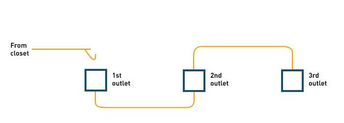
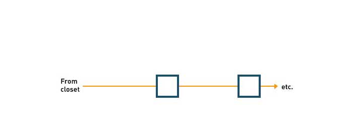
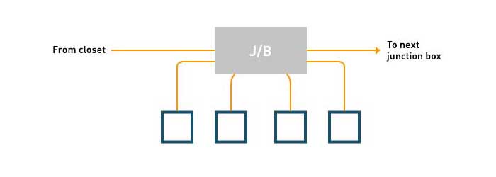
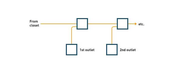
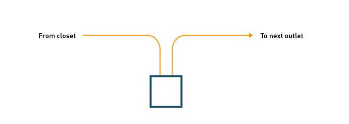
568: 4.4.2.6.3 states “Boxes shall be placed in a straight section of conduit and not used in lieu of a bend.” The corresponding conduit ends should be aligned with each other. Refer to the diagram AA, Figures A, B & C, are three, traditional methods of horizontal conduit distribution, none are 568 compliant. Figure D, is compliant, however it would only be practical for use as a ceiling pull box, Figure E , would be the only compliant way to run conduits for horizontal distribution, and be able to have one homerun conduit serving three outlets.
Conduit Bends
There are two aspects of conduit bends for discussion, number (of bends) in one run, and radius. As we will see the 569 standard is much more stringent on both of these aspects, than the NEC.
Number in One Run
NEC 346-11: “There shall be no more than the equivalent of four quarter bends (360 degrees total) between pull points, e.g., conduit bodies and boxes.”
TIA/EIA-569, 4.4.2.1: “No section of conduit shall be longer than 30m (100ft) or contain more than two 90 degree bends between pull points or pull boxes.
Bear in mind that the NEC rule applies to high voltage circuits as well as low voltage. High voltage can be 10, 25, or 50KV (10,000 volts, 25,000 volts and 50,000 volts, respectively). If these highly sensitive, high voltage cables, can be safely installed by following 346-11, then why can’t low voltage cables? Why put a distance restriction? Communication cable may be sensitive, but it is not quite a string of egg shells. It would be interesting to know if the 569 committee did any studies on the stresses, and their effects, that a communication cable will undergo when pulled into conduits, under various conditions. Were the guidelines based on hard facts, or just the rule of thumb that a major amount of overkill will surely get the job done?
Radius of Bends
To comply with the NEC, you need only use a standard conduit bending devise, or purchase pre-fabricated bends. Manufacturers of conduits and their bending apparatuses, make their products to comply with the NEC table 346-10. The NEC 346-10, has only two categories: Conductors without lead sheath, and, Conductors with lead sheath. Lead sheathed cables, once commonly used for electrical service entrances, have all but been replaced by newer insulation’s. For our purposes, we will only refer to the column for Conductors without lead sheath.
On bend radius, the TIA/EIA-569, 4.4.2.2, states the following:
“The inside radius of a bend in a conduit shall be at least 6 times the internal diameter. When the conduit size is greater than 50mm (2 inches), the inside radius shall be at least 10 times the internal diameter of the conduit. For fiber optic cable, the inside radius of a bend shall always be at least 10 times the internal diameter of the conduit”
To compare the NEC’s standards to those of the TIA/EIA-569, I have compiled the following chart. The chart has three columns. The numbers in the columns indicate radiuses, expressed in inches. Since standard conduit bends comply with the NEC, the first column, labeled “standard” refers to NEC guidelines. Column 2, indicates 6 times the conduit’s internal diameter, as recommended by the 569 standard for communication cables (except fiber optics) pulled in conduits 2” or less. Column 3 indicates ten times the conduit’s internal diameter, as mandated by 569, for fiber optics, and conduits over 2”. For our customers, we sell pre-terminated fiber optic cables so they are able to connect them in their installation more easily.
| EMT Conduit Size Standard 6 x Diameter 10 x Diameter | |||
|---|---|---|---|
| ½” | 4” | 3.73” | 6.22” |
| ¾” | 4.5” | 4.94” | 8.24” |
| 1” | 5.75” | 6.29” | 10.49” |
Notes:
The chart above is based on the internal diameters of EMT conduit. Fractions of an inch are expressed in a decimal format, rounded to the nearest hundredth of an inch.
Numbers in red are higher than the standard radii, required by NEC 346-10.
As we can see by the chart above, the only standard bend that complies with the “six times” rule is for ½” EMT. All other conduit sizes would require custom bending. In addition, most of the radiuses listed in the “ten times” column, would be cumbersome to handle and install, to say the least.
In Conclusion
As a medium, conduit is a viable and practical distribution system for many applications. Unfortunately, the 569 standard, all but eliminates the words “viable and practical”. I think most would agree that some changes need to be made to the 569 standard, pertaining to conduit installations. If you use the information presented here along with some good common sense, you should be able to attain a trouble free and professional installation.