

 Technical Note
These shielded Cat 6A Jacks are extremely easy and quick to install. We wrote these instructions in many steps so as to give our
customers a very detailed assembly instruction. Most users will have no trouble installing this jack in two minutes or less.
1 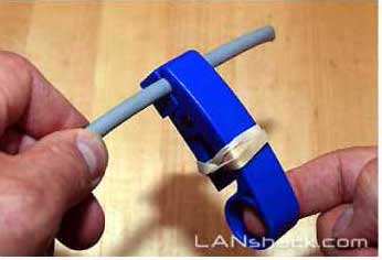
Skin the cable about 2 inches back. If you are using our E-Z UTP stripper tool on a very thick wire like Cat 6 shielded, you can adjust the cutting depth by putting a rubber band on the handle to reduce the cutting pressure. |
2 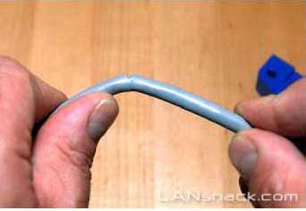
Gently bend the cable's jacket back and forth to free it and remove that portion of the jacket. |
3 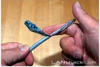
Gently bend the foil back over the end of the cable's jacket. The foil may be brittle and crack off completely. If this happens, you can try re-skinning the insulation. If you still can't prevent the foil from cracking off, the |
4 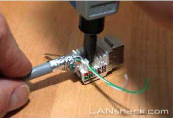
Cut the foil about ¼" back and bend it around the diameter of the jacket. The foil will not cover the entire jacket. That is normal and not a problem. |
5 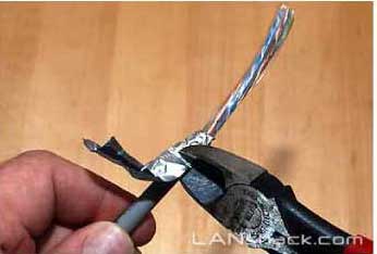
Take the drain wire and wrap it around the foil. |
6 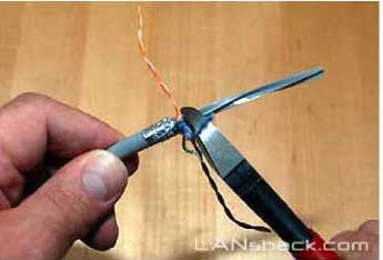
Bend back the four pairs and cut the center spline. It is not necessary to get a completely flush cut as attempting to do so may damage the conductors. |
7 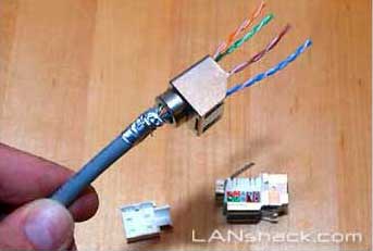
Slide the metallic shield over the cable with the open end facing the end of the cable. Slide it several inches back as to make room for the termination of the cable to the jack. |
8 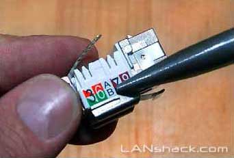
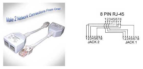
Follow the color code that is on the side of the jack. Take note that the Orange and Green pairs are shown in alternate positions for 568-A or 568-B wiring. Choosing "A" or "B" will not be of any consequence so long as you |
9 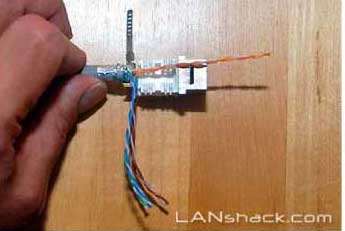
Prepare to terminate the pairs by positioning the end of the skinned jacket very close to the back end of the jack. This is important for two reasons: |
10 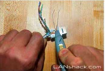
Position each twisted pair in the slots where they will be terminated. Untwist the cable's pairs in such a way as they will be twisted all the way up to the point of termination. |
11
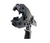
Double check the wiring sequence and then use a "110" termination tool to terminate the wires. Be sure to: |
12 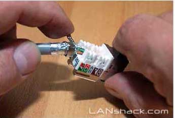
Once all of the wires are terminated, make the shield connection by slipping the ground strip into the locking groove. |
13 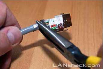
Use a pair of pliers to pull the ground strip all the way until it grabs the drain wire (and / or foil). Wrap the remainder of the ground strip around itself. |
14 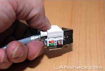
Secure the plastic cap over the terminations. |
15 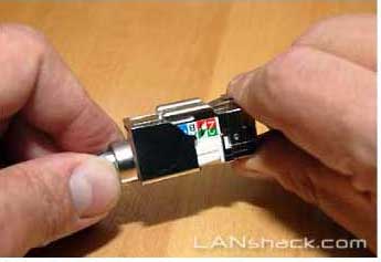
Slide the metallic shield over the jack all the way up until it locks in place. Once the other end of the cable is terminated, test the cable from end to end with a cable tester. Be sure that all eight conductors plus the ground |
Notes Regarding Making Category 6 Patch Cable:
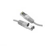
- The RJ-45 plugs are normally made for either solid conductors or stranded conductors. It is very important to be sure that the plug that you use matches the conductor type. It is extremely difficult to tell the difference between the two by looking at them. When you buy these plugs, be sure to categorize, and store them carefully. Using the wrong type can cause intermittent problems. The QuickTreX™ Category 5E, 8 Conductor Modular Plugs , OR QuickTreX™ Category 6, 8 Conductor Modular Plugs that we sell are rated for both Solid and Stranded cable.
- Ordinarily, it would be taboo to untwist the pairs of any category 5 or 6 cable. The one exception to this rule is when crimping on RJ-45 plugs. It would be impossible to insert the wires into the channels without first untwisting and straightening them. Be sure not to extend the un-twisting, past the skin point. If you do it properly, you will wind up with no more than 1/2" of untwisted conductors (up to 1/2" of untwist meets the cat 5 or 6 specification).
- If the completed assembly does not pass continuity, you may have a problem in one, or both ends. First try giving each end another crimp. If that does not work, then carefully examine each end. Are the wires in the proper order? Do all of the wires fully extend to the end of the connector? Are all of the pins pushed down fully. Cut off the suspected bad connector, and re-terminate it. If you still have a problem, then repeat the process, this time giving more scrutiny to the end that was not replaced.
Not shown above is this keystone jack. This wallplate includes a duplex singlemode keystone jack and a CAT 6A keystone jack
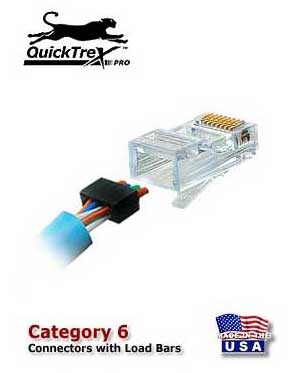
It is now not only possible but also easy to field terminate Category 6 modular plugs thanks to the new QuickTreX™ Category 6 modular plug which contains a new Patented Conductive NEXT Reduction System. The Conductor Loading Bar is molded from a material that substantially reduces the affect of NEXT within the Plug Body. The conductors are isolated by plastic that absorbs the NEXT from between the conductors and channels it away so that the Plug can perform to Category 6 levels. When assembled onto Category 6 compliant patch cable it will pass all TIA/EIA requirements for NEXT and Return Loss. This will help your Category 6 channel maintain increased headroom to assure your network operates at its best.
Controversies and Caveats: Category 5, 5E, and Cat 6 Patch Cables
568B vs. 568A
For patch cables, 568-B wiring is by far, the most common wiring method. Virtually all pre-assembled patch cables are wired to the B standard. There is no difference in connectivity between 568B and 568A cables. Therefore, a 568B patch cable should work fine on a 568A cabling system, and visa-versa.
Re-use of old cables
We have seen this happen time and time again. Perfectly good patch cables that have been working fine for years, get removed from their installation, and re-installed on the same, or different network. The result can be a nightmare. What happens is that the cable, over time, adapts to the way that it is bent in it's original installation. When these cables are removed and re-installed, they can either completely lose their connection, or develop intermittent problems. This is due to stresses that may be opposite to what they were originally subject to. If the integrity of your network is more valuable than the price of new patch cables, then we strongly suggest that you use brand new cables for all closet cleanups, network moves, etc.
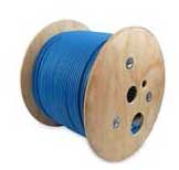
Stranded vs. Solid wire
Almost all patch cables that are made have stranded wire. Stranded wire is normally specified for use in patch cables due to its superior flexibility. There has been some talk recently, in the technical sector of the structured wiring community, regarding the possible use of solid conductors for patch cables. The reason for the spotlight on solid wire is that it is supposedly more stable, under a variety of conditions. Please note that we now offer custom Solid copper category 5E patch cables in Plenum insulation in lengths of up to 295 feet. These cables are suitable for use in air handling (Plenum) ceilings and environments.